









Harmonic Drive Reducer / Strain Wave Generator Gear box
The academic term for harmonic drive is strain wave gearing; based on its physical characteristics, it can also be called a harmonic reducer or harmonic gear. The harmonic drive principle was invented by the outstanding American inventor C.W. Musser and was put into practical application in Japan in 1964. HONPINE company started producing harmonic reducers in 2018 and has continuously optimized the tooth profile. At the end of the 20th century, China began researching the relevant theories and engaging in industrial production. The most significant feature of the harmonic reducer is that it consists of only three basic components: a rigid gear, a flexible gear, and a wave generator. This makes it easy to achieve miniaturization and lightweight design. Due to the large number of teeth involved in the meshing process, it can achieve significant torque transmission and precise control. Currently, there are more than 20 types of harmonic reducers, with a torque range from 1 Nm to 2000 Nm.
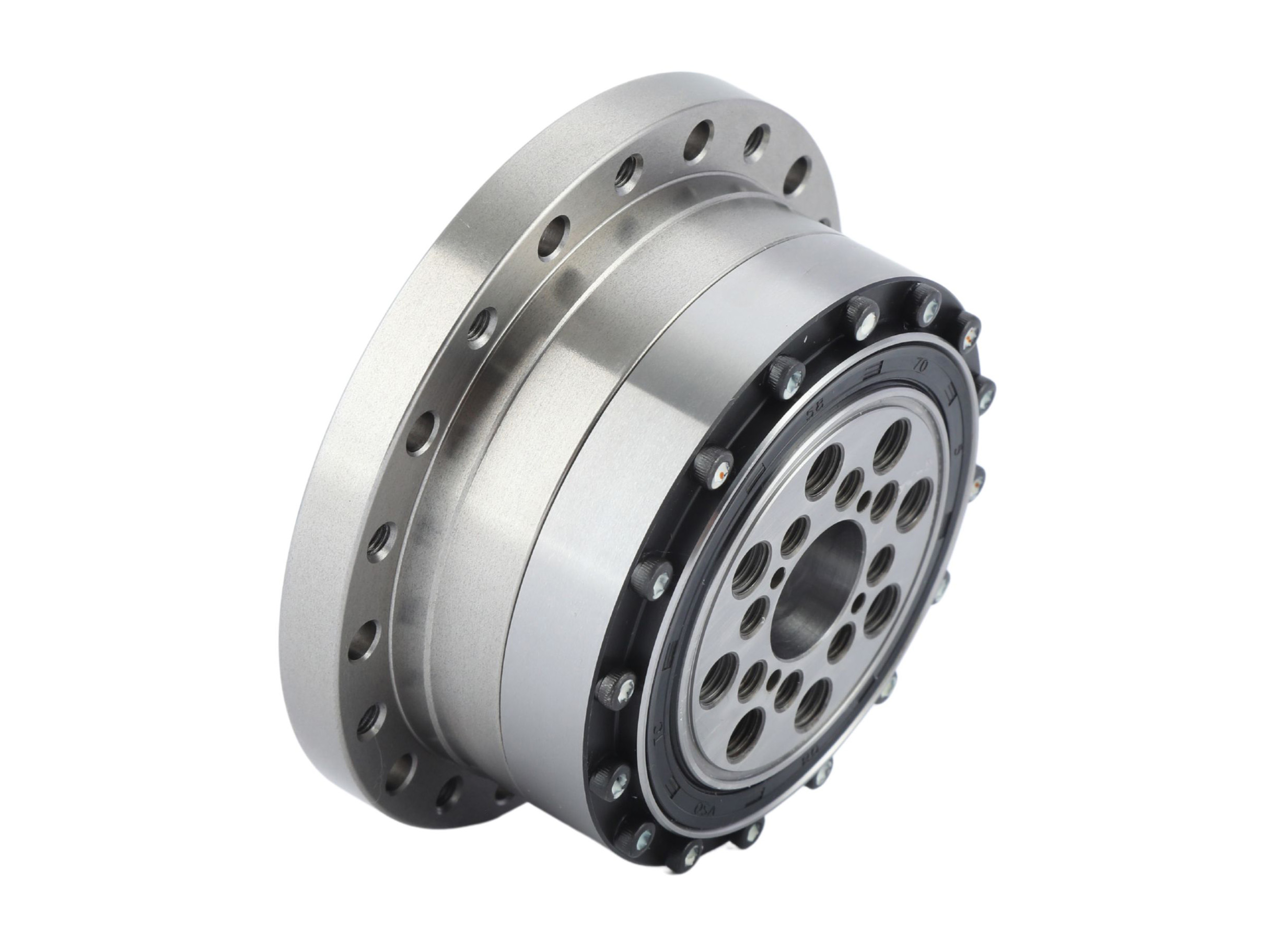
Standard Harmonic Drive Gear Box
Standard harmonic reduction gear are the most commonly used and widely applied category among all types of harmonic reduction gear. Standard products are mass-produced and sold, resulting in controllable overall costs and stable precision. This major category includes the FSG series, FHG series, FHD series, FSD series, and FDS series.
 Sealed Flange Structure Input Shaft Harmonic DriveThe FHG-IV series harmonic drive features an input shaft configuration. It adopts an integrated sealed flange structure that combines harmonic drive components into a single unit, internally filled with specialized lubricating grease for simplified equipment integration. A high-rigidity cross roller bearing (main bearing) is integrated within the assembly. It is typically configured with either fixed circular spline and flexspline output or fixed flexspline and circular spline output.Details
 Easy Installation Large Hollow Shaft Structure Harmonic DriveThe FHG-III series harmonic drive features a large hollow shaft structure. It adopts an integrated sealed flange design that combines harmonic drive components into a single unit, pre-filled with specialized lubricating grease for simplified equipment assembly. A high-rigidity cross roller bearing (main bearing) is integrated internally. This system is typically configured with either fixed circular spline and flexspline output or fixed flexspline and circular spline output.Details
 High Rigidity High torque High Precision Strain Wave DriveThe FHG-II series strain wave drive features a cross roller bearing coupling structure for its wave generator, allowing for automatic fine-tuning of coaxiality. The size of the cam shaft hole can be adjusted according to the customer's motor model, with the input shaft directly fitting into the inner bore of the wave generator and connected via a flat key. It incorporates a built-in high-rigidity cross roller bearing (main bearing). Generally, it is used with the rigid wheel end fixed and the flexspline end output, or with the flexspline fixed and the rigid wheel end output as the connection method.Details
 Coaxial Input and Output Strain Wave Gear BoxThe FHG-I series strain wave gear box features an integrated cam structure for its wave generator. The size of the cam shaft hole can be adjusted according to the customer's motor model, with the input shaft directly fitting into the inner bore of the wave generator and connected via a flat key. It incorporates a built-in high-rigidity cross roller bearing (main bearing). Generally, it is used with the rigid wheel end fixed and the flexspline end output, or with the flexspline fixed and the rigid wheel end output as the connection method.Details
 Easy Installation Strain Wave Gear for Robot Arm and Sealed Rotary TablesThe FSG-II series strain wave gear utilizes a cross slider coupling mechanism for its wave generator. The cam shaft bore dimensions can be customized to accommodate specific motor models. The input shaft directly engages with the wave generator’s inner bore through a keyed connection. This configuration is typically implemented with the circular spline fixed at the base and the flexspline serving as the output end.Details
 Easy Installation Strain Wave Gear Support Custom Design to Match Motor ModelsThe FSG-I series Strain wave gear employs an integrated cam-type wave generator. The cam shaft bore dimensions can be customized to match customer-specific motor models. The input shaft directly interfaces with the wave generator's inner bore via a keyed connection. This system is typically configured with the circular spline fixed at the base and the flexspline functioning as the output end.Details
 Ultra Thin Compact Design Hat Shape Light Weight Harmonic ReducerThe FHD Series harmonic reducer employs an ultra-short top-hat flexspline design, designed for applications demanding extreme compactness and lightweight performance.The FHD Combined Type pursues the ultimate flat-profile design. Compared to the FHG series, its axial length is reduced by approximately 50%. Equipped with high-rigidity cross roller bearings on the output side, it is ideally suited for applications requiring space-constrained designs.Details
 Compact Cup Type Harmonic Gear for Aerospace,Robot,LCD Panel,Semiconductor EquipmentThe FSD series harmonic gear adopts an ultra-short cup-type flexspline structural design, achieving approximately 50% shorter axial length compared to the FSG series. It is specifically designed for applications requiring extreme compactness and weight reduction.
In recent years, emerging fields such as humanoid robots, aerospace systems, along with LCD panel and semiconductor manufacturing equipment, have been pursuing ultra-thin solutions under the strict spatial limitations of production line systems.
Building on the lightweight and compact features of harmonic gear transmissions, the FSD series meets market demands by retaining the proven performance of traditional products while implementing bold structural innovations.Details FDS Ultra Compact Design Harmonic Drive Gear with High TorqueThe differential gear FDS series is divided into the combined type and the component type. The combined type aims to integrate the differential mechanism into a single unit for easy assembly into equipment, and its housing allows direct mounting of transmission gears, pulleys, etc. The component type pursues a flat and thin design, enabling customers to design their own encapsulation housing and optimize device space according to their structural requirements.
Utilizing Harmonic Drive's unique operating principle, it is an ultra-compact differential device capable of performing phase and timing fine-tuning during operation.
The combined type of the FDS series shares the same four core components as the pancake component type, except that the combined type includes additional front and rear sealing flanges and support bearings. The FDS series operates on the same working principle as the cup-type FSG series. The shape of the pancake flexspline is identical to the cross-section of the cup flexspline's base, and the wave generator bearings are arranged in two rows, with the tooth width of the circular spline and flexspline increased to handle higher torque capacity. Additionally, the pancake type incorporates an extra circular spline with the same number of teeth as the flexspline for connection to the output shaft.Details
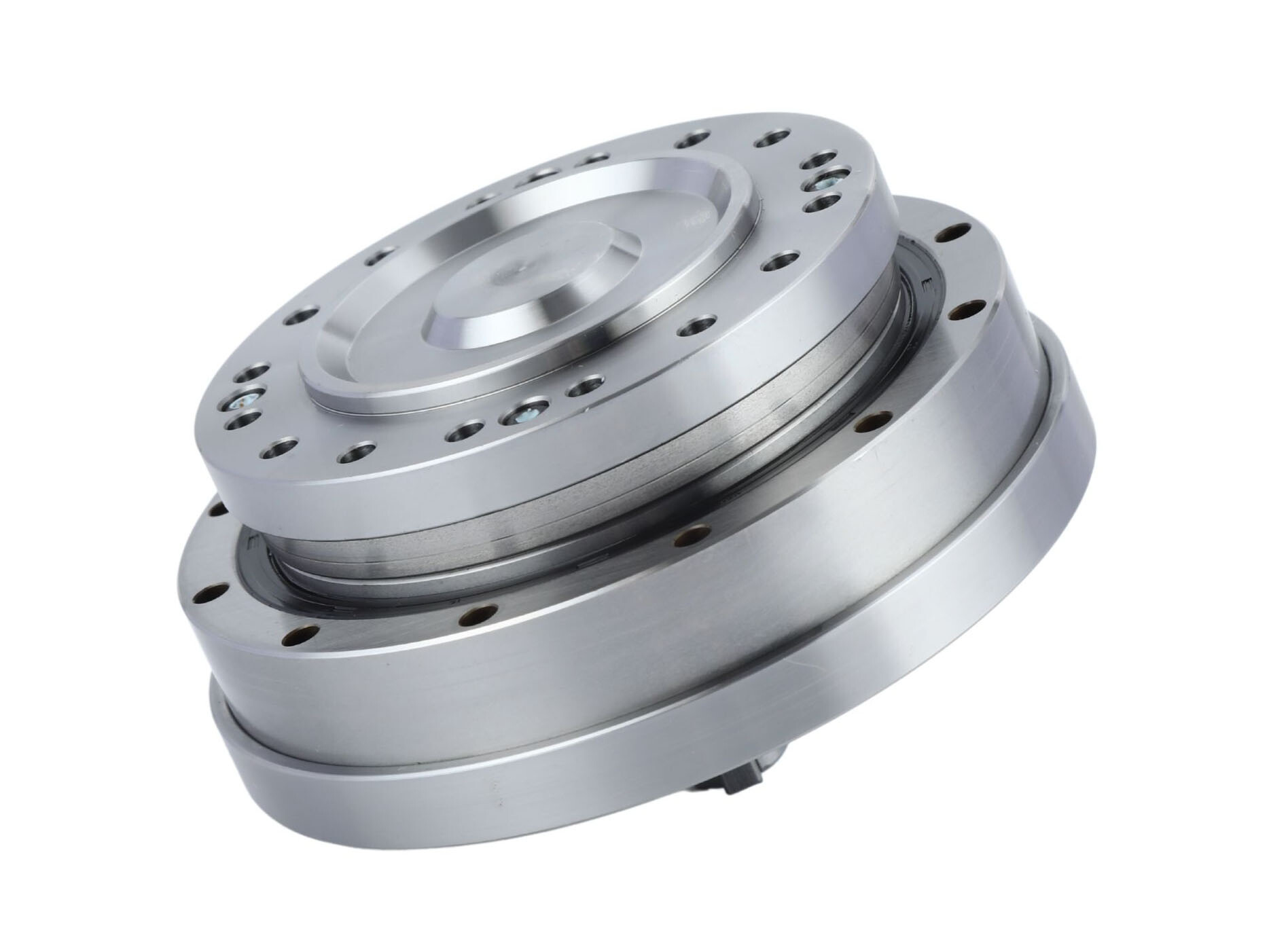
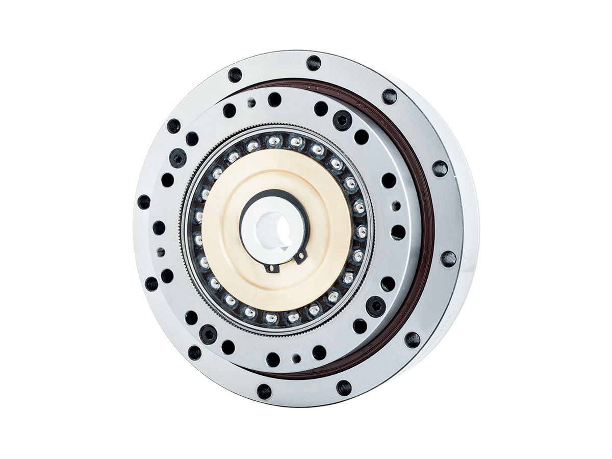
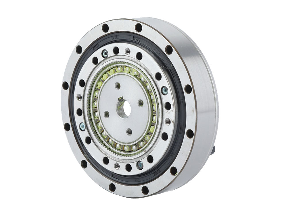
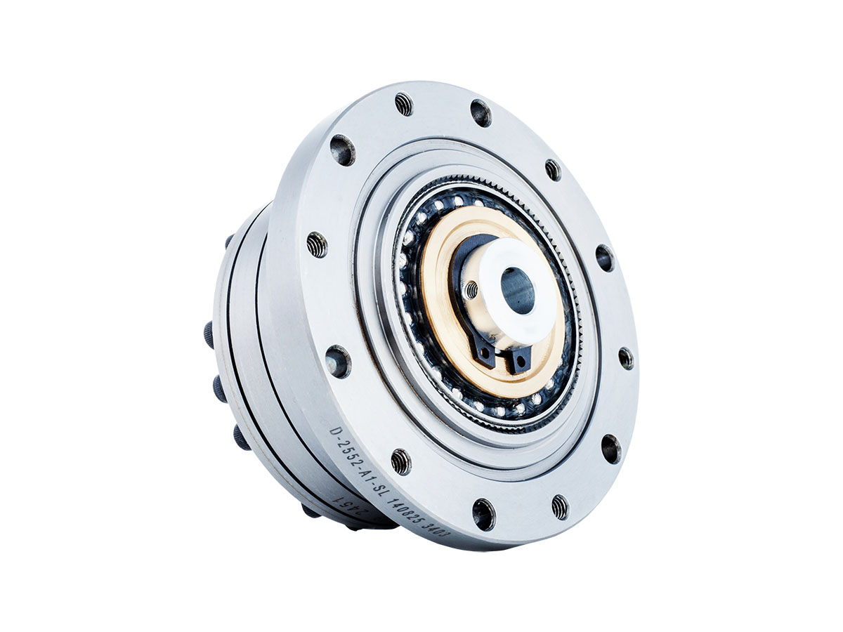
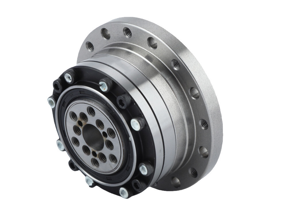
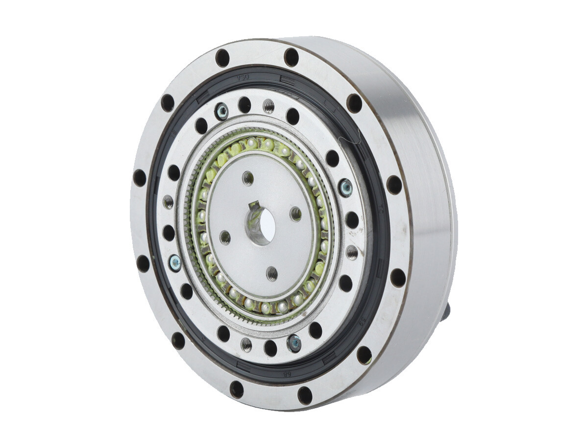
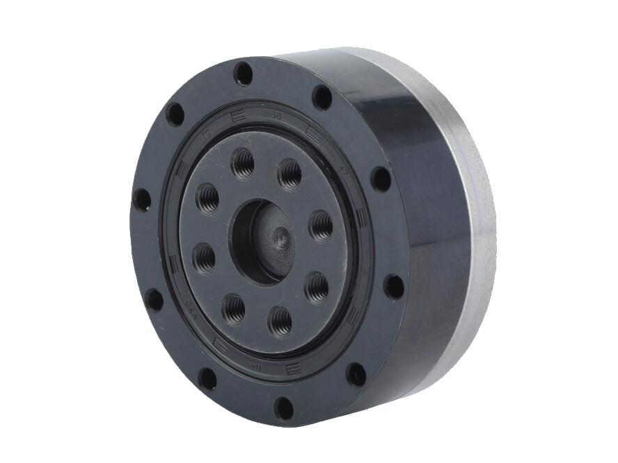
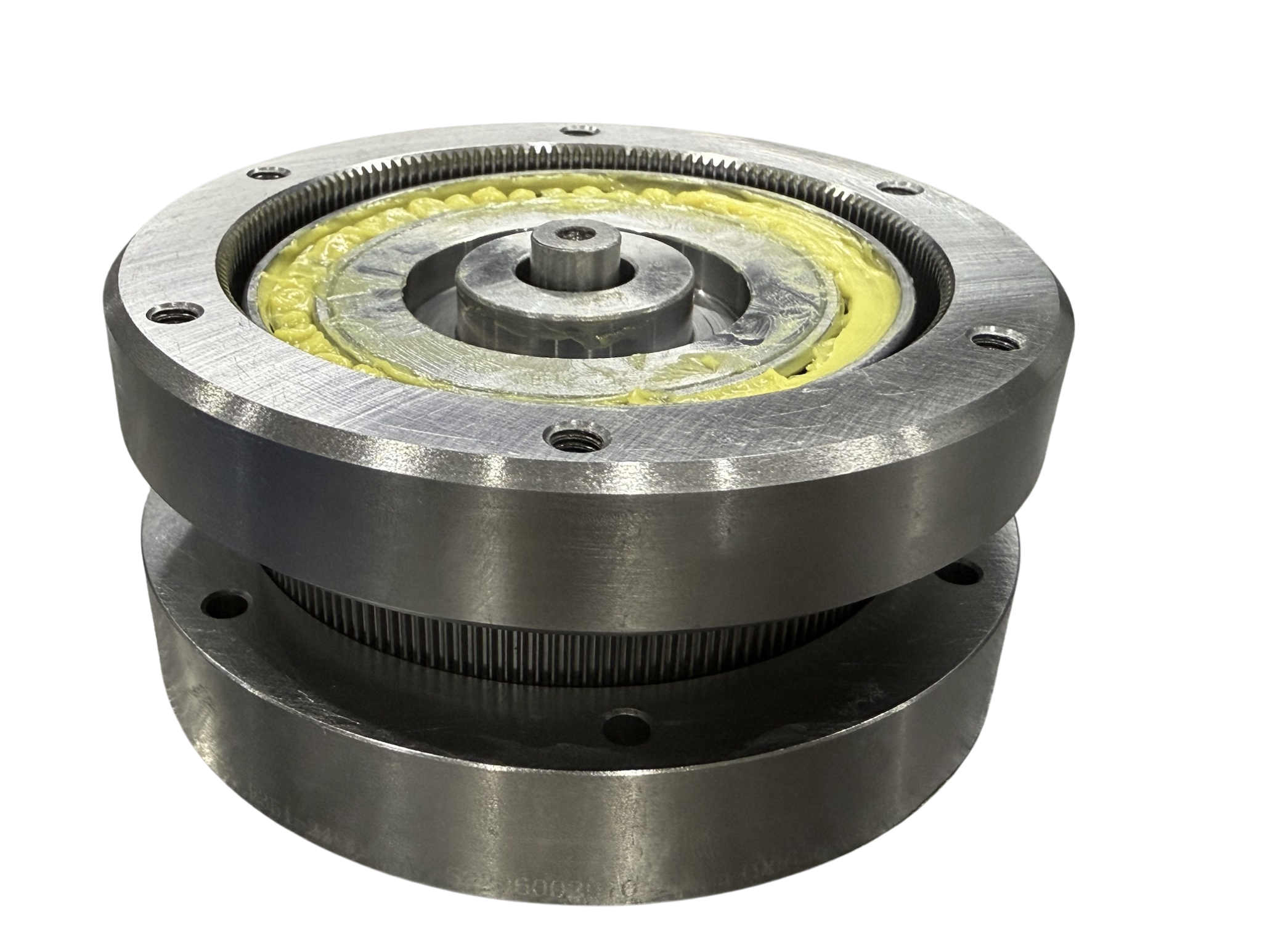
Flange Strain Wave Harmonic Drive
Standard harmonic reduction gear are the most commonly used and widely applied category among all types of harmonic reduction gear. Standard products are mass-produced and sold, resulting in controllable overall costs and stable precision. This major category includes the FSG series, FHG series, FHD series, FSD series, and FDS series.
 High Rigidity Motor Shaft Flange Harmonic Drive ReducerThe LHSG-RDP series harmonic drive reducer is developed on the high-rigidity FHG-I platform to accommodate customers requiring direct motor integration. It incorporates pre-machined motor shaft connection holes and motor mounting flanges, with the gear unit factory-sealed with specialized lubricating grease. This series typically adopts a fixed flexspline end and an output circular spline end directly coupled to the motor during operation. It offers exceptional convenience for applications demanding both direct motor connection and enhanced harmonic drive rigidity – customers can achieve immediate usability by simply aligning the motor shaft and tightening the fasteners post-purchase. This design optimizes installation efficiency while maintaining structural robustness for high-stiffness direct-drive scenarios.Details
 Direct Motor Connection Flange Harmonic Reduction GearThe LCSG-RDB harmonic reduction gear series is designed based on the FSG-I platform to facilitate direct motor connection for customers. It features pre-designed motor shaft connection holes and motor mounting flanges, with the gear reducer internally sealed with special lubricating grease at the factory. This series typically employs a fixed circular spline end and an output flexspline end directly coupled to the motor during operation. It provides exceptional convenience for applications requiring direct motor connection and custom sealing flanges - customers can simply secure the motor connection with screws for immediate use after procurement. This design streamlines integration while maintaining sealing integrity for users with direct-drive requirements.Details
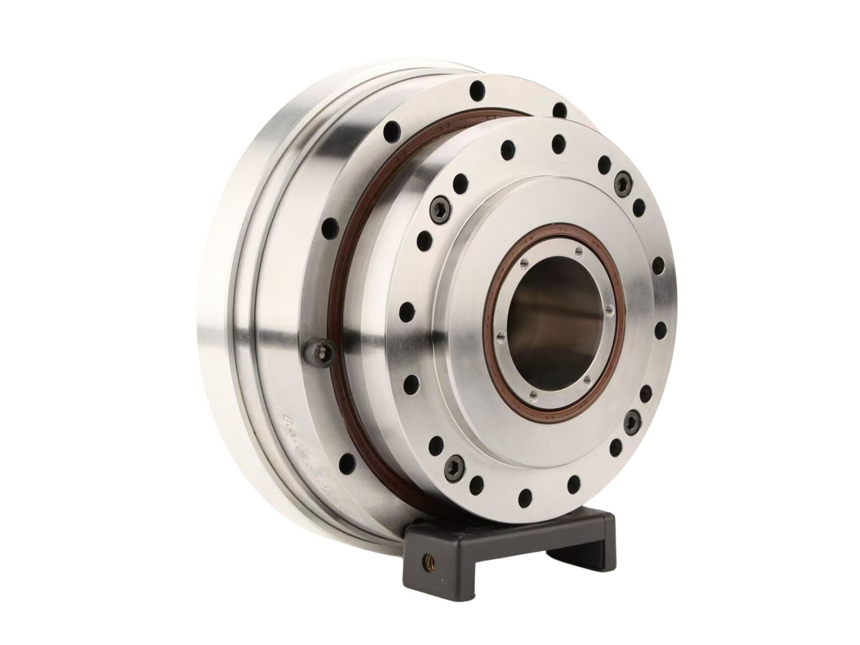
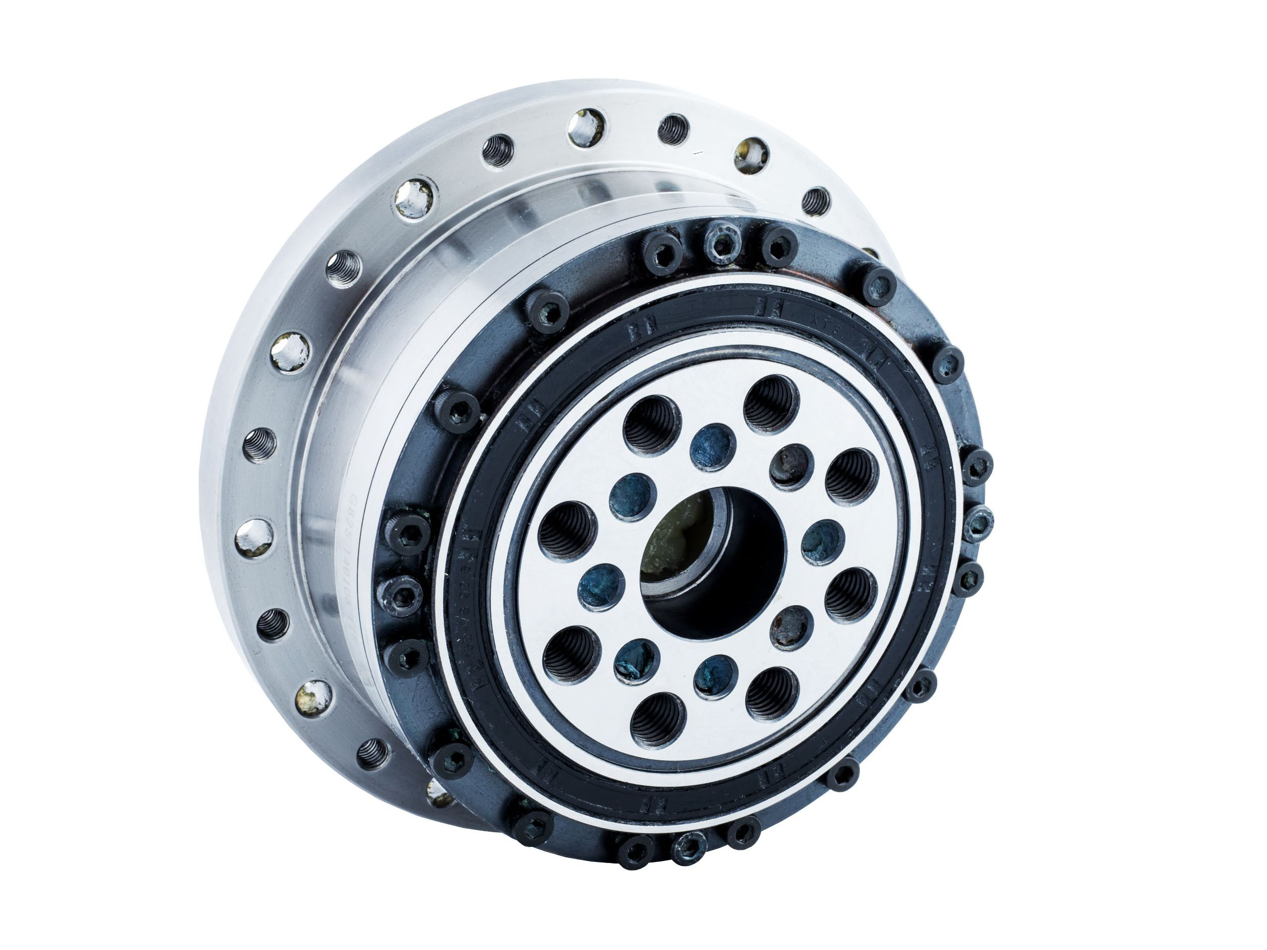
Large Harmonic Drive Gearbox
Extra-Large Harmonic drives are designed and manufactured for customers with special torque and size requirements in the harmonic reducer series. These harmonic reducers offer greater torque, higher rigidity, and stronger load capacity. This series includes:
High-torque cup-style flexspline models: FCG-45-AJ, FCG-50-AJ, FCG-58-AJ, FCG-65-AJ;
High-torque top-hat flexspline models: FHG-45-SJ, FHG-50-SJ, FHG-58-SJ, FHG-65-SJ;
High-torque top-hat flexspline models with large hollow sealed structures: FHG-45-AH, FHG-50-AH, FHG-58-AH, FHG-65-AH.
 Compact Design High Torque Heavy Load Strain Wave GearboxThe FHG-SJ series strain wave gearbox is engineered for high-torque and heavy-load applications, featuring compact axial dimensions compared to conventional reducers. It incorporates a top-hat style flexspline and an integrated cam wave generator, where the cam shaft bore is customizable to match specific motor models. The input shaft directly interfaces with the wave generator’s inner bore via a keyway connection. This series typically employs a fixed flexspline end and an output circular spline end configuration.Details
 High Torque Hat Style Large Hollow Shaft Harmonic Reduction GearThe FHG-AH series harmonic reduction gear is engineered for high-torque, large hollow shaft, and heavy-load applications. Featuring a top-hat style flexspline and a wave generator cam with an oversized hollow shaft structure, this series enables effortless routing of cables, lead screws, and optical pathways through its central cavity, effectively addressing challenges associated with passing large components. It delivers an optimized solution for such requirements. The series typically employs synchronous pulley connections or large hollow shaft gear structures for input integration.Details
 High Torque Heavy Load Cup Style Strain Wave GearThe FCG-AJ series strain wave gear is engineered for high-torque and heavy-load applications. It adopts a cup-style flexspline and an integrated cam wave generator, where the cam shaft bore can be customized to match specific motor models. The input shaft directly interfaces with the wave generator's inner bore via a keyway connection. This series typically employs a fixed circular spline end and an output flexspline end configuration.Details
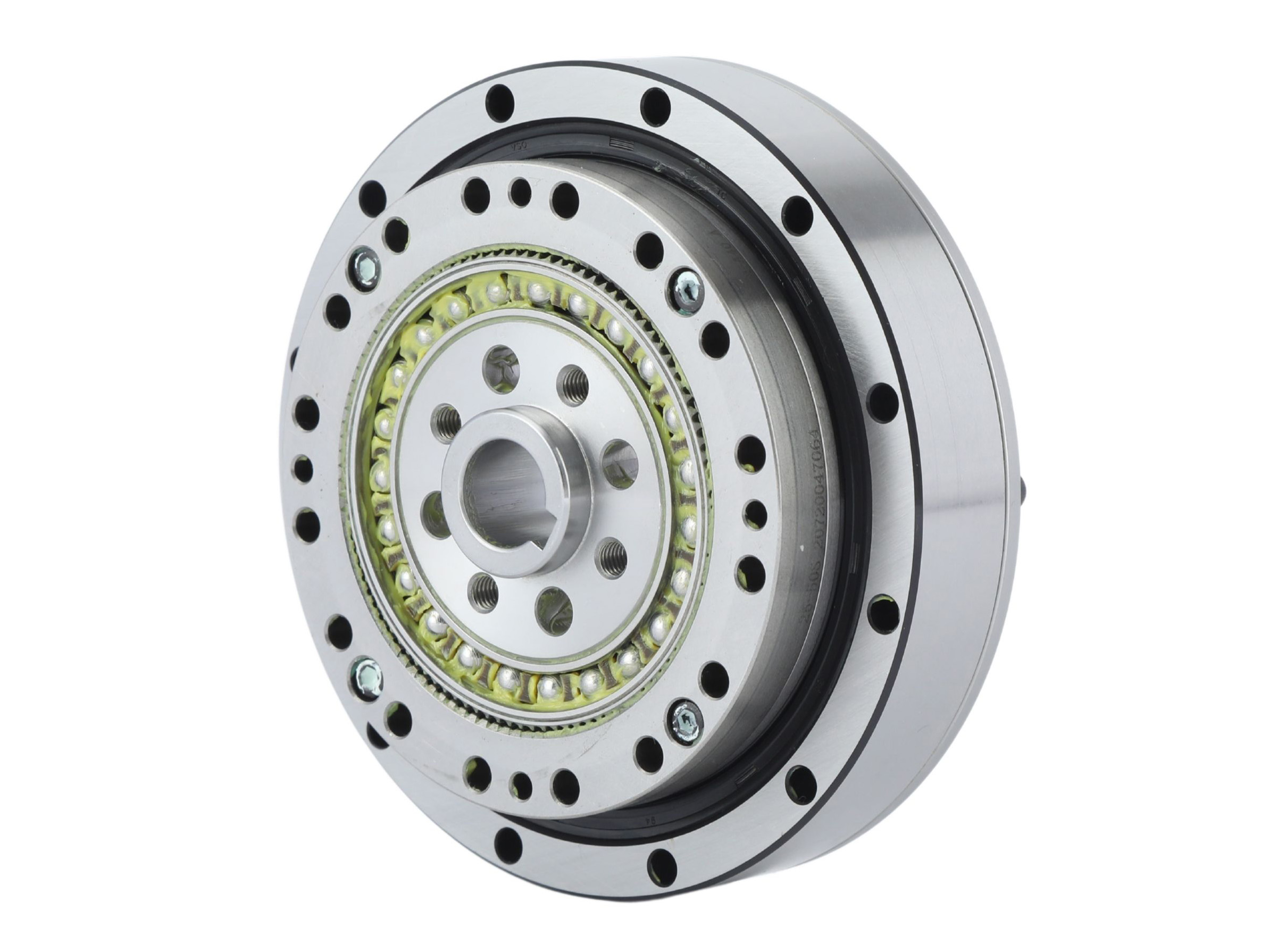
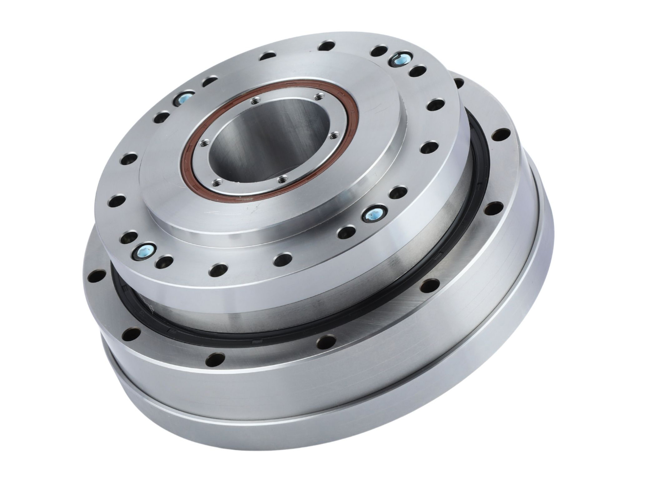
Mini Harmonic Drive Gear
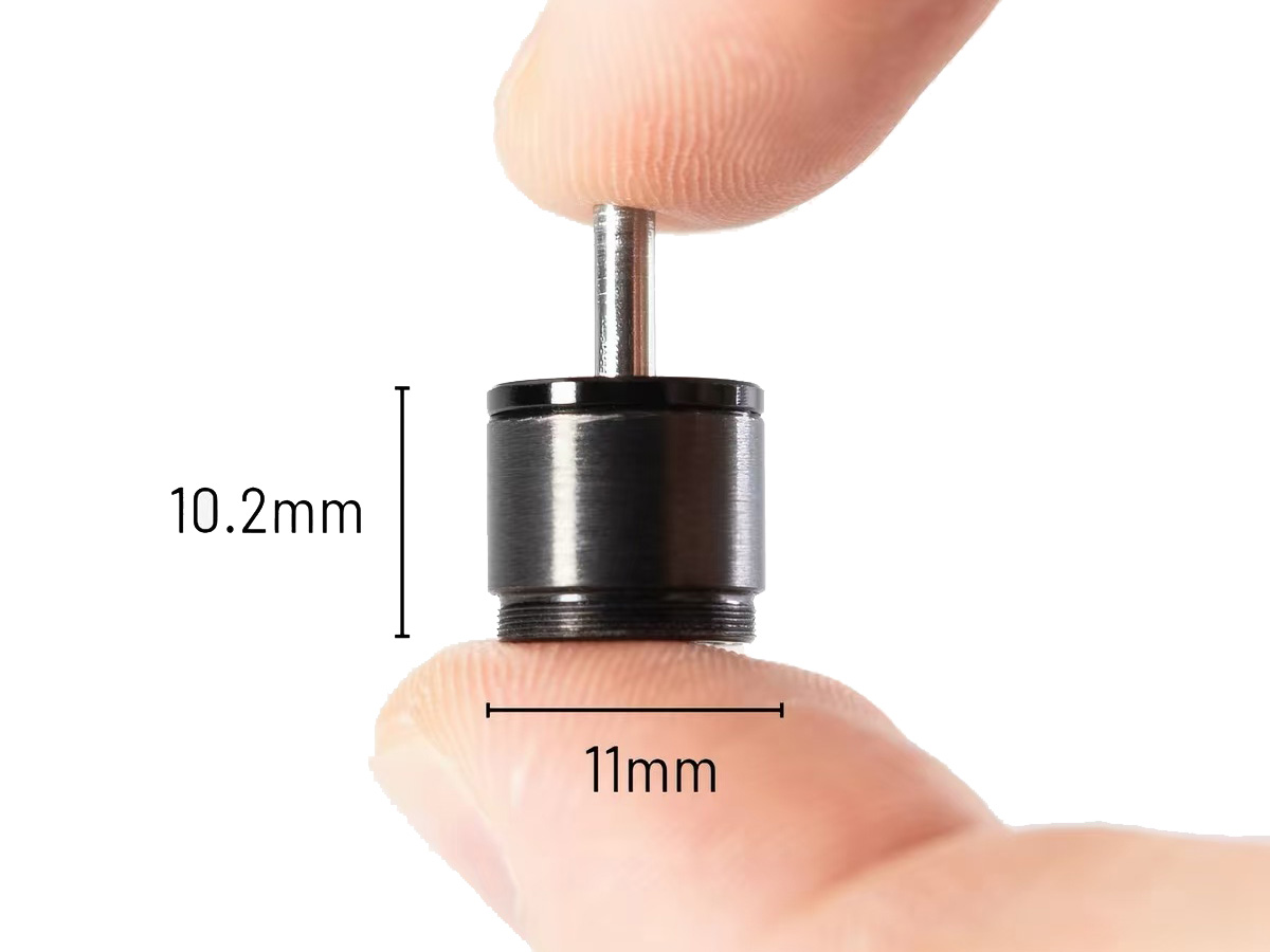
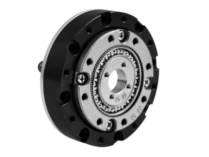
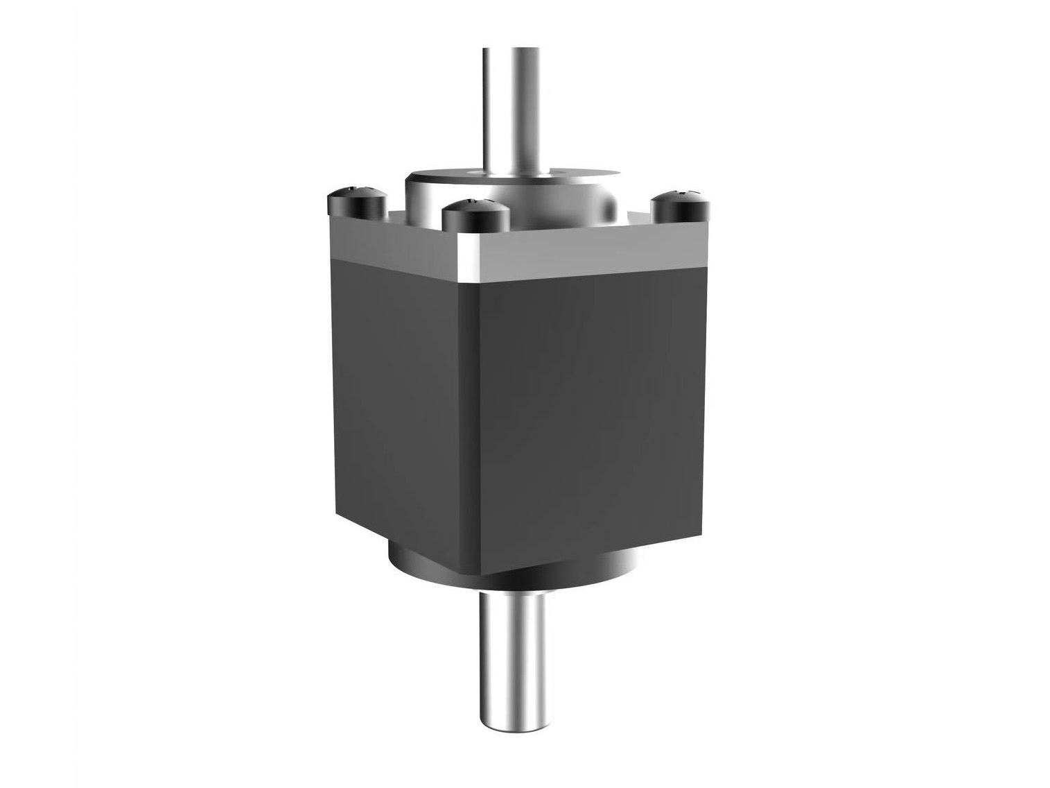
The micro harmonic drive series is designed and manufactured for customers with special requirements for compact size and lightweight in the harmonic drive reducer family. These reducers feature smaller dimensions, lighter weight, and high precision. This series includes the CSF-mini series with cup-style flexspline structures and the SHD-mini series with top-hat flexspline structures. The CSF-mini series offers multiple input/output configurations, such as shaft input, bore input, shaft output, and flange output. Currently, these products are mass-produced and sold with stable and reliable precision.
 Micro Harmonic Drive Reducer for Humanoid Robot HandsHumanoid robot hands require highly flexible and precise movements while maintaining a compact, lightweight structure. They also need low operating noise, high torque density, and long-term reliability. Considering these requirements, the HONPINE CSF Micro Harmonic Drive Reducer is an ideal transmission solution for humanoid robot hands and dexterous robotic fingers.
Compact design: The small and lightweight structure makes it easier to integrate into the limited space of humanoid robot hands and finger joints.Details Top Hat Style Compact Axial Dimensions Small Harmonic DriveThe SHD-mini series harmonic drive is designed for applications with small volume and weight requirements, featuring compact axial dimensions and a top-hat style flexspline. This series exclusively supplies pre-assembled modular products for immediate use. The main bearing employs compact four-point contact ball bearings to directly support external loads. The shaft bore dimensions in this series can be customized to match specific motor shaft sizes. Select the most suitable motor model based on your mechanical design requirements.Details
 Cup Stype Compact Design Lightweight Miniature Harmonic driveThe CSF-mini series miniature harmonic drive is developed for applications with specialized volume and weight requirements, utilizing a cup-style flexspline. This series exclusively offers pre-assembled modular products for immediate use. The main bearing employs compact four-point contact ball bearings to directly support external loads. The CSF-mini series includes two types: the motor-mount type (2XH) and the shaft-input type (1U) that supports input forms such as belts, gears, and couplings. Select the most suitable model based on your mechanical design requirements.Details
What is Harmonic Drive Reducer?
Structure of a Harmonic Drive Reducer
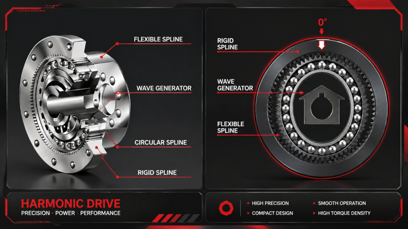
A harmonic drive reducer consists of three core components:
Circular Spline:
A rigid internal gear with two more teeth than the flexspline (e.g., 102 teeth vs. 100 teeth). The tooth profile is typically involute or double circular arc.
Flexspline:
A thin-walled, cup-shaped metal component with external teeth. It is elastically deformable and capable of withstanding repeated cyclic deformation.
Wave Generator:
An elliptical or polygonal cam combined with a flexible bearing, which drives the flexspline to deform periodically.
Working Principle
When the wave generator rotates, it forces the flexspline to deform from a circular shape into an elliptical shape. At the ends of the major axis, the teeth of the flexspline fully engage with those of the circular spline, while at the ends of the minor axis, the teeth disengage.
As the wave generator continues to rotate, the engagement zones between the flexspline and circular spline continuously shift, creating a “tooth difference transmission” effect. This results in a reduction in output speed.
Thanks to this unique mechanism, a harmonic drive reducer can achieve a high single-stage reduction ratio ranging from 1/30 to 1/320, while maintaining extremely high transmission accuracy (typically less than 1 arc-minute of error).
HONPINE Harmonic Drive Reducer Introduction
This video provides a brief overview of the HONPINE harmonic drive reducer product categories. For more selection guidance, please contact us to obtain the most comprehensive product catalog.
Advantages of Harmonic Drive Reducer
Harmonic reducers are widely used in industries such as robotics, CNC equipment, medical equipment, industrial automation, and semiconductor equipment due to their advantages such as high precision, low backlash, and compact design. This section elaborates on the advantages of harmonic reducers.
High Precision & Zero Backlash
Harmonic drive reducers deliver exceptional positioning accuracy thanks to their near-zero backlash design. The unique elastic engagement between the flexspline and circular spline eliminates mechanical play, ensuring precise motion control and excellent repeatability. This makes them ideal for high-precision applications such as robotics, CNC rotary tables, and semiconductor equipment.
High Torque Density
Harmonic drive reducers provide outstanding torque output relative to their size. The multi-tooth engagement mechanism distributes load across multiple teeth simultaneously, enabling high torque transmission in a compact form factor. This results in improved efficiency and makes them well-suited for applications requiring high torque in limited installation space.
Compact & Lightweight Design
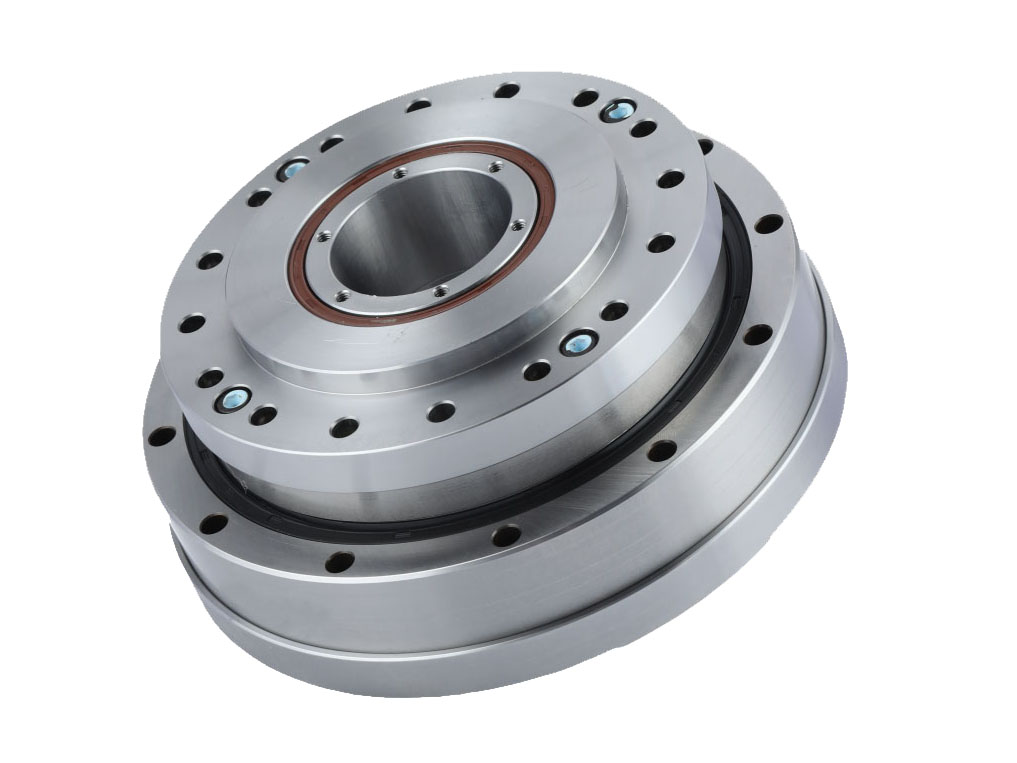
With a high reduction ratio achieved in a single stage, harmonic drive reducers offer a significantly more compact and lightweight solution compared to conventional gear systems. Their space-saving design allows for easier integration into compact machinery and robotic joints, reducing overall system size while maintaining high performance.
Long Service Life
Designed for durability and reliability, harmonic drive reducers feature optimized tooth geometry and high-quality materials that ensure long operational life. The smooth transmission and reduced wear characteristics minimize maintenance requirements, allowing for consistent performance over extended periods, even under demanding operating conditions.
Harmonic Gear Reducer FAQ
A harmonic gear consists of three main components: the flexspline, circular spline, and wave generator.
The operating principle is based on the elastic deformation of the flexspline and the misaligned meshing motion of the gears. The wave generator forces the flexspline to deform elliptically, causing the external teeth of the flexspline to engage sequentially with the internal teeth of the circular spline. This continuous differential engagement produces a high reduction ratio.
The gear ratio of a harmonic drive reducer is determined by the tooth count difference (ΔZ) between the flexspline (Zf) and the circular spline (Zg), transmission mode (double-wave or multi-wave), tooth matching rules, and structural design constraints. These ratios are not random but are based on mature engineering standards widely used in the industry.
Double-wave transmission (ΔZ = 2)
This is the most commonly used configuration due to high meshing efficiency, uniform wear, and long flexspline service life.
Core formulas:
Flexspline output (circular spline fixed):
i = Zf / (Zg − Zf) ≈ Zf / ΔZ
(When ΔZ = 2, i ≈ Zf / 2)
Circular spline output (flexspline fixed):
i = Zg / (Zg − Zf) ≈ Zg / ΔZ
(When ΔZ = 2, i ≈ Zg / 2)
Common Tooth Count and Ratio Examples
Ratio Output Mode Tooth Count (Zg / Zf) Calculation
30 Flexspline output 62 / 60 60 ÷ (62 − 60) = 30
50 Flexspline output 102 / 100 100 ÷ (102 − 100) = 50
100 Flexspline output 202 / 200 200 ÷ (202 − 200) = 100
101 Circular spline out
Avoid selecting an excessively low reduction ratio, and never exceed the rated input speed.
Lower harmonic drive reduction ratios generally provide lower torsional stiffness and slightly larger backlash, making them less suitable for high-precision positioning applications.
For laser equipment, precision automation, collaborative robots, and harmonic drive gear reducers for robots, standard reduction ratios such as 80:1, 100:1, and 120:1 are often preferred because they provide an excellent balance between rigidity and positioning accuracy.
In addition, always ensure that the servo motor speed remains within the gearbox's allowable input speed. Excessive speed increases heat generation, accelerates wear, and shortens the lifespan of the harmonic gear drive.
Lightweight design, higher precision, improved fatigue resistance, and better torque density for humanoid robotics and smart manufacturing.
When selecting a harmonic drive reducer, you should first determine the specific application industry and installation position, then define the following parameters:
Required reduction ratio
Input and output speed
Rated torque and peak torque
Accuracy requirements
Installation method
Space constraints
Providing these details helps ensure accurate and reliable selection.
HONPINE currently offers five main categories of harmonic reducers:
Direct drive harmonic reducers
Hollow type harmonic reducers
Input shaft type harmonic reducers
Ultra-thin harmonic reducers
Mini harmonic reducers
With a complete range of models and tooth profiles, HONPINE products can meet the needs of most customers. If standard models cannot meet specific requirements, customization is supported.
Each core component of our harmonic reducers is manufactured in dedicated workshops, making HONPINE one of the most capable manufacturers for harmonic reducer customization.
Pricing is provided on a one-to-one basis according to the specific model and required quantity.
Contact us:
WhatsApp: +86 189 9432 9920
Email: sales@honpine.com
We need to confirm the exact model and quantity based on your application requirements, and then check inventory availability.
Contact us:
WhatsApp: +86 189 9432 9920
Email: sales@honpine.com
If the required harmonic reducer is in stock, shipment can usually be completed within one week.
If there is no stock, the delivery time will be determined based on the specific model, quantity, and HONPINE factory production schedule.
Contact us:
WhatsApp: +86 189 9432 9920
Email: sales@honpine.com
In most cases, the problem is insufficient torsional rigidity—not insufficient torque.
Every harmonic gear reduction mechanism experiences a small amount of elastic deformation during operation.
Under rapid reversing or frequent start-stop conditions, insufficient torsional stiffness can cause vibration, positioning drift, and rebound.
For precision positioning systems, choose high-rigidity harmonic gearboxes with minimal backlash and low transmission error to ensure stable repeatability.
Yes. HONPINE is a professional harmonic drive reducer manufacturer. You are welcome to contact us to schedule a factory visit.
Contact us:
WhatsApp: +86 189 9432 9920
Email: sales@honpine.com
Improper installation can shorten the life of any harmonic reducer.
Even the highest-quality harmonic drive gears cannot compensate for poor installation.
A harmonic gear drive reducer requires excellent alignment between the servo motor, gearbox, and load. Poor concentricity generates bending moments that continuously overload the flexspline and bearings, resulting in:
Excessive heat
Abnormal noise
Premature wear
Reduced service life
For long cantilever applications, auxiliary bearing support is recommended. Depending on installation requirements, choose the appropriate hollow shaft, flange, or solid shaft configuration.
Prioritize sealing, lubrication, and service life.
Applications involving dust, shock loads, high temperatures, welding, or laser cutting environments place additional stress on harmonic reducers.
Avoid selecting products based solely on minimum specifications.
Instead, choose:
Sealed versions
Specialized lubricants
Regular maintenance schedules
Periodic grease replacement
These measures help prevent contamination, reduce wear, and maximize the operating life of your harmonic drive gearbox.
If you are looking for a reliable harmonic reducer supplier or harmonic reducer supplier in China, be sure to evaluate sealing technology, lubrication systems, and long-term durability—not just catalog specifications.
Avoid these six common engineering mistakes.
The majority of gearbox failures can be prevented by avoiding the following errors:
Ignoring dynamic inertia and considering only static load
Checking rated torque while overlooking peak torque
Ignoring torsional rigidity in high-precision applications
Using an insufficient safety factor under impact loads
Poor alignment between the motor, gearbox, and driven equipment
Choosing a lower harmonic drive reduction ratio simply to reduce costs
By avoiding these common mistakes, engineers can eliminate most field issues, including abnormal noise, vibration, poor positioning accuracy, and premature gearbox failure.
As a professional harmonic reducer factory and harmonic drive reducer factory, Honpine specializes in the development and manufacturing of high-performance harmonic drive gear reducers for robots, industrial automation, semiconductor equipment, medical devices, and precision motion systems.
Whether you need a standard harmonic gear reducer for sale, customized harmonic reduction gear, or engineering support for selecting the optimal harmonic drive gearbox, our experienced team is ready to help.
Contact Honpine today to learn more about our precision harmonic gearboxes, harmonic drive gears, and complete motion control solutions for robotics and industrial automation.
Harmonic drive is also known as a harmonic gearbox, harmonic reducer, or strain wave gearbox. These different names originate from its unique working principle and its original naming when the technology was first invented.
Simply put, “strain wave” describes the physical principle, while “harmonic drive” is the more widely recognized commercial name.
Origin of the Term “Strain Wave”
The core of a harmonic drive is a thin-walled elastic component called the flexspline. During operation, it is deformed by an elliptical component known as the wave generator.
This deformation creates a periodic “strain”, which refers to the material’s elastic deformation under stress. This deformation is the fundamental mechanism through which power is transmitted.
As the wave generator rotates, the deformation region continuously propagates along the flexspline in a smooth, wave-like motion—similar to ripples moving across water—thereby driving the gear engagement and producing motion.
Origin of the Term
The model number of a harmonic reducer contains information about the series, size, reduction ratio, mounting type, and structure.
Example: LHSG-40-121-C-III
LHSG — High torque standard cylindrical harmonic reducer series
40 — Frame size (approximately 4-inch pitch diameter)
121 — Reduction ratio of 121:1
C — Mounting configuration code
III — Hollow structure with center through-hole for cable routing
The exact naming rules may vary depending on the manufacturer. Always refer to the official product catalog before selecting a harmonic gearbox.
Yes. HONPINE is a professional harmonic drive reducer manufacturer. You are welcome to contact us to schedule a factory visit.
Contact us:
WhatsApp: +86 189 9432 9920
Email: sales@honpine.com
No. Harmonic reducer naming systems are not universal.
Different manufacturers, such as Harmonic Drive Systems, Leaderdrive, and other precision reducer manufacturers, may use similar naming logic, but the meaning of each letter and number can be different.
For accurate selection, engineers should always check the corresponding manufacturer's product specifications and catalogs.
Pricing is provided on a one-to-one basis according to the specific model and required quantity.
Contact us:
WhatsApp: +86 189 9432 9920
Email: sales@honpine.com
Understanding torque specifications is important when selecting a harmonic reducer for robot joints and automation equipment.
Rated Torque
The continuous torque that the harmonic reducer can operate under at the specified input speed (for example, 2000 rpm).
Start/Stop Peak Torque
The short-term allowable torque during acceleration, deceleration, starting, or stopping.
Maximum Average Load Torque
The maximum allowable average torque under variable operating conditions. Exceeding this value may cause overheating, lubricant degradation, and accelerated wear.
Maximum Instantaneous Torque
The maximum short-duration torque caused by external impact loads. It is mainly used for safety verification.
We need to confirm the exact model and quantity based on your application requirements, and then check inventory availability.
Contact us:
WhatsApp: +86 189 9432 9920
Email: sales@honpine.com
Maximum Input Speed
The highest input speed that the harmonic reducer can withstand for a short period.
Average Input Speed
The equivalent weighted average speed under variable speed operation.
Both values must remain within the specified limits. Excessive speed may cause increased temperature, lubricant deterioration, and mechanical wear.
Harmonic reducer selection usually includes four key steps:
1. Speed Matching
Match the motor speed with the required output speed.
2. Torque Matching
Ensure that the maximum load torque is lower than the allowable peak torque.
3. Inertia Matching
Check the reflected load inertia ratio to ensure it is within the recommended range.
4. Rigidity Matching
Verify tilting rigidity and stiffness under offset or uneven load conditions.
Correct selection helps improve the performance and service life of harmonic gearboxes in robotic and automation applications.
Different applications require different harmonic reducer structures:
Standard applications:
Choose cup-type or standard cylindrical series, such as LCS/LHS.
Heavy-duty applications:
Select high torque models with the "G" designation.
Cable routing requirements:
Choose hollow structure models (III).
Space-limited applications:
Select short-length or lightweight models, such as CL series.
Technically, yes. However, different robot joints have different requirements.
For the base and shoulder joints (J1/J2), RV reducers are usually recommended because they provide:
Higher rigidity
Better impact resistance
Higher load capacity
For wrist joints (J4–J6), harmonic reducers are more suitable because of:
Compact size
High precision
Low weight
High reduction ratio
A hybrid solution using RV reducers and harmonic reducers is common in industrial robots.
Operating above the recommended average load torque may cause:
Early lubricant degradation
Abnormal gear wear
Increased operating temperature
Reduced reducer service life
Engineers should always verify operating conditions during harmonic reducer selection.
To select the correct harmonic reducer model, engineers should provide:
Payload weight
Operating speed or angular velocity
Acceleration and deceleration time
Repeat positioning accuracy requirement
Installation space limitations
Working temperature
Requirement for center cable routing
Providing complete application parameters helps ensure reliable performance.
The moment of inertia is used to calculate dynamic torque during acceleration and deceleration.
It helps engineers match:
Motor inertia
Load inertia
System response performance
Motion stability
The inertia value listed in product catalogs usually refers to the inertia measured on the wave generator input shaft.
Correct inertia matching improves the response speed and stability of robotic joint systems.
A harmonic drive reducer (harmonic gearbox) is a precision transmission device that uses elastic deformation of a flexible spline to achieve high reduction ratios. It consists of a wave generator, flexspline, and circular spline, widely used in robot joints and robotic actuators.
It works through controlled elastic deformation. The wave generator deforms the flexspline into an ellipse, creating alternating tooth engagement with the rigid spline. Continuous rotation produces slow reverse output, achieving high reduction ratios.
Because they offer high reduction ratio (50–300), near-zero backlash, coaxial structure, lightweight design, and high precision, making them ideal for collaborative robots, humanoid robots, and robotic joint modules.
High precision (up to 30 arc-sec), compact size, high torque density, smooth motion, low noise, and strong multi-tooth engagement ensure stable performance in robot joint systems and automation equipment.
Flexspline fatigue under shock loads, higher manufacturing cost, limited low-ratio applications, and thermal constraints due to compact structure.
Harmonic: ultra-precision & lightweight; Planetary: balanced cost & durability; RV: high rigidity & heavy load. Harmonic is best for upper robot joints and precision motion.
No. Load inertia must also be calculated.
Many engineers focus only on equipment weight when selecting a harmonic drive gearbox, but dynamic inertia is often the real challenge. High-frequency start-stop cycles, rapid acceleration, and reversing motion generate significant inertial loads, especially in cantilever structures and rotating robot joints.
The larger the rotation radius, the greater the inertia amplification effect. Ignoring inertia calculations can result in positioning errors, vibration, backlash growth, and even premature flexspline fatigue failure.
When selecting harmonic gear reducers or a strain wave reducer, never rely solely on load weight.
Torque rating, reduction ratio, precision (≤1 arc-min or 30 arc-sec), lifetime, backlash, noise, and environmental resistance.
Always evaluate both rated torque and peak torque.
Rated torque determines whether a harmonic reduction gear can operate continuously under normal working conditions, while peak torque determines its ability to withstand acceleration, emergency stops, and impact loads.
For high-inertia robotic joints or automation equipment, a safety factor of 2.0 or higher is generally recommended.
Keep in mind that peak torque is intended only for short-duration overloads. Operating a harmonic gear box continuously at peak torque will significantly reduce its service life.
Regular lubrication checks, temperature monitoring, load control, and vibration/noise inspection ensure long service life.
What are Applications of Harmonic Drive Reducer?
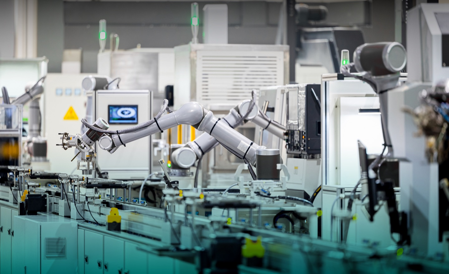
Harmonic drive reducers for industrial robotics are widely used in high-precision motion control systems where accuracy is the top priority, followed by service life, transmission ratio, and efficiency. They are commonly integrated into robot joints such as shoulders, elbows, and wrists, enabling high repeat positioning accuracy, smooth trajectory control, and reliable long-term operation in demanding industrial environments.
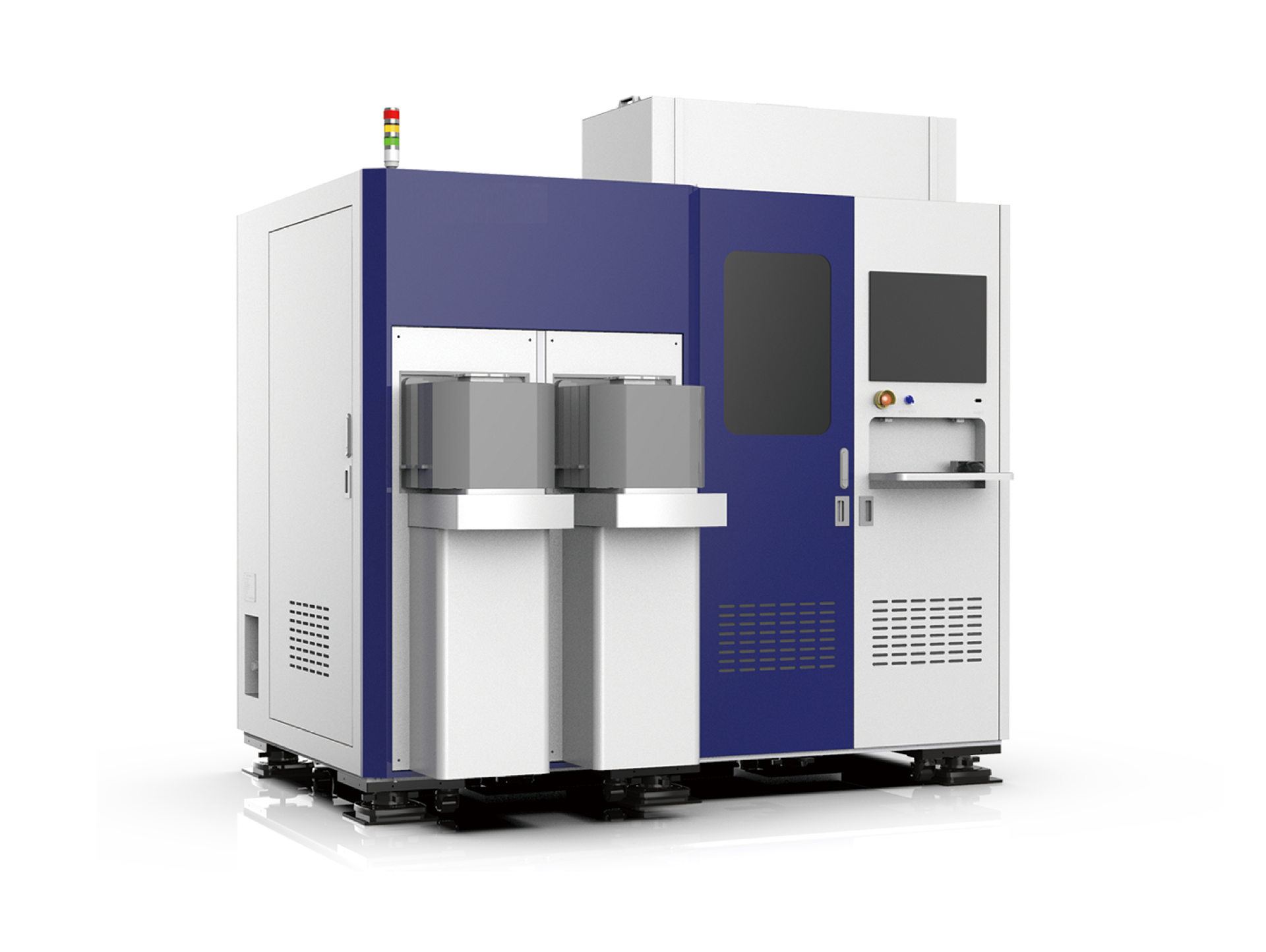
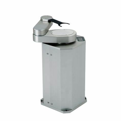
Harmonic drive reducers for semiconductor equipment play a critical role in ultra-precision systems where thermal stability is essential. In these applications, temperature rise control is the primary concern, followed by precision and durability. They are widely used in wafer handling, alignment, and inspection systems to ensure stable performance and minimize thermal drift that could affect nanometer-level positioning accuracy.
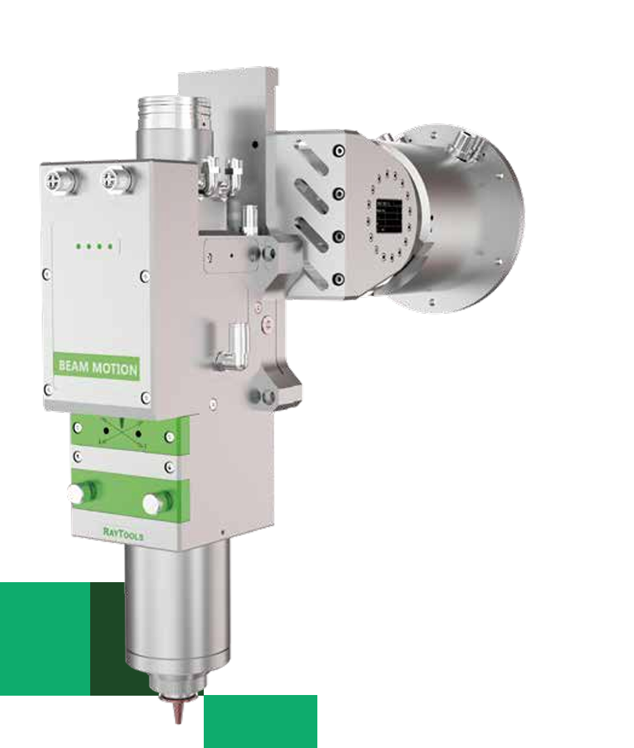
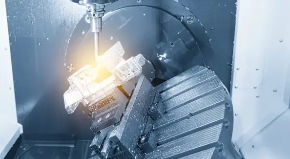
Harmonic drive reducers for CNC machines are increasingly used in rotary tables, indexing heads, and multi-axis machining systems where high precision and zero backlash are required. Their ability to deliver smooth motion, high positioning accuracy, and compact structure makes them ideal for improving surface quality and machining consistency in advanced CNC applications.
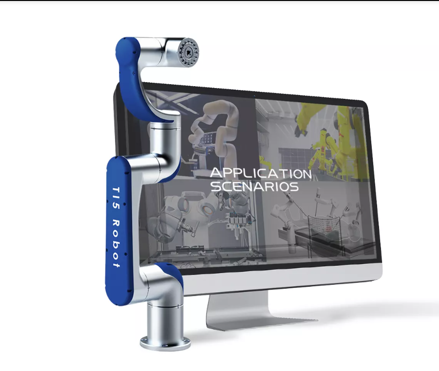
Harmonic drive reducers for collaborative robots are designed with a focus on lightweight construction, followed by transmission ratio and cost efficiency. These features allow them to meet the requirements of human-robot interaction systems, providing compact integration, safe operation, and smooth motion control while maintaining affordability and flexibility for various industrial tasks.
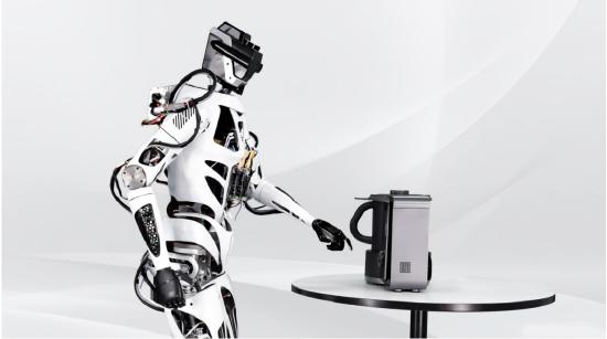
Harmonic drive reducers for humanoid robots are becoming increasingly important as robotic systems require more natural, human-like motion in complex multi-joint structures. Their compact size, high torque density, and zero-backlash characteristics make them ideal for joints such as shoulders, elbows, wrists, and ankles, enabling smooth movement coordination, high responsiveness, and stable dynamic performance in humanoid designs.
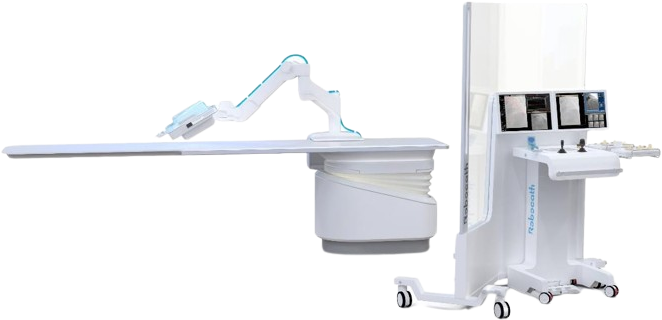
Harmonic drive reducers for medical equipment are widely used in surgical robots, imaging systems, and precision medical devices where accuracy, smooth motion, and low noise are essential. Their ability to provide high positioning precision and stable operation ensures safe and reliable performance in sensitive medical environments, particularly in minimally invasive surgical applications.
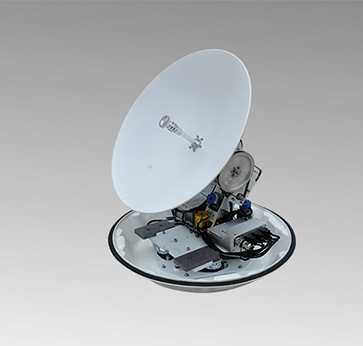
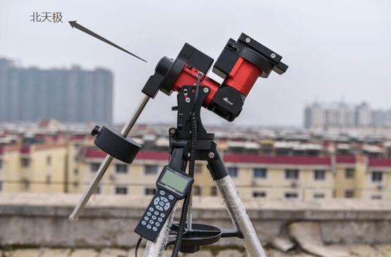
Harmonic drive reducers for aerospace applications prioritize reliability above all, followed by load capacity and precision. They are used in demanding systems such as satellite antenna mechanisms, space robotic arms, and flight control actuators, where stable performance must be maintained under extreme conditions and long operational lifecycles.
Across all these applications, harmonic drive reducers deliver a unique combination of high precision, zero backlash, compact design, and high torque density, making them a core solution in modern advanced motion control systems.
‹
›
How Has HONPINE Harmonic Reducer Technology Laid the Foundation for Harmonic Drive Actuator Development?
In the field of harmonic reducer technology, HONPINE has continuously optimized product performance since successfully developing its first 3D conjugate double-arc tooth profile precision reducer in 2017.
This proprietary tooth profile design helps improve transmission accuracy, extend service life, and reduce noise and vibration, while also providing a strong technical foundation for the future integration of torque sensors.
Currently, HONPINE harmonic reducers can achieve:
transmission accuracy below 40 arc-seconds,
backlash less than 10 arc-seconds,
and precision retention exceeding 10,000 hours.
All critical components undergo heat treatment and hard finishing processes to ensure product consistency and long-term reliability.
In addition, HONPINE has invested in the six-axis force sensor company Haibosen Technology, further strengthening its independent R&D capabilities and supply chain advantages in the field of “reducer-integrated torque sensors.”
Advanced Manufacturing and Quality Control Capabilities of Harmonic Drive Reducer
In manufacturing, HONPINE has introduced multiple internationally advanced machining and inspection systems.
For gear manufacturing, a gear skiving process is adopted, enabling component precision above Grade 5 standards. Combined with a full-process quality control system — including coordinate measuring machines (CMM), gear measuring centers, and roundness measuring instruments — HONPINE ensures both ultra-high precision and stable large-scale production capability.
At the same time, supported by its independently controlled R&D system and supply chain integration capabilities, HONPINE has achieved in-house development and production of nearly all core components, excluding only basic raw materials such as chips, copper, and steel.
For different application scenarios including industrial automation and service robots, HONPINE can provide customized solutions focused on either:
high-load capacity,
or lightweight design,
meeting the robotics and intelligent equipment industries’ demands for safe, reliable, and modular precision transmission components.
With coordinated manufacturing operations across production bases in Suzhou and Shanghai, HONPINE harmonic reducers have achieved industry-leading product specifications and manufacturing standards.