








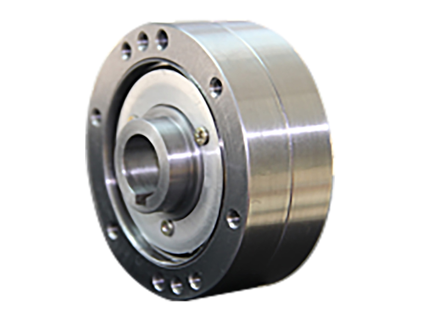
FDS Ultra Compact Design Harmonic Drive Gear with High Torque
● Introduction
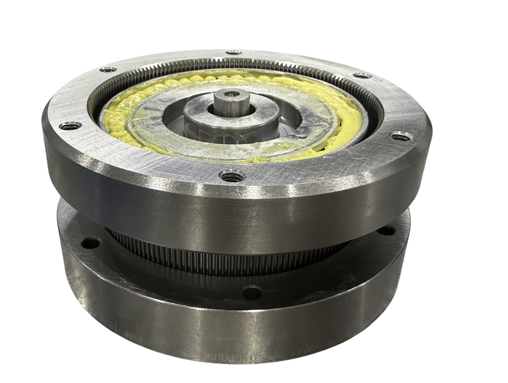
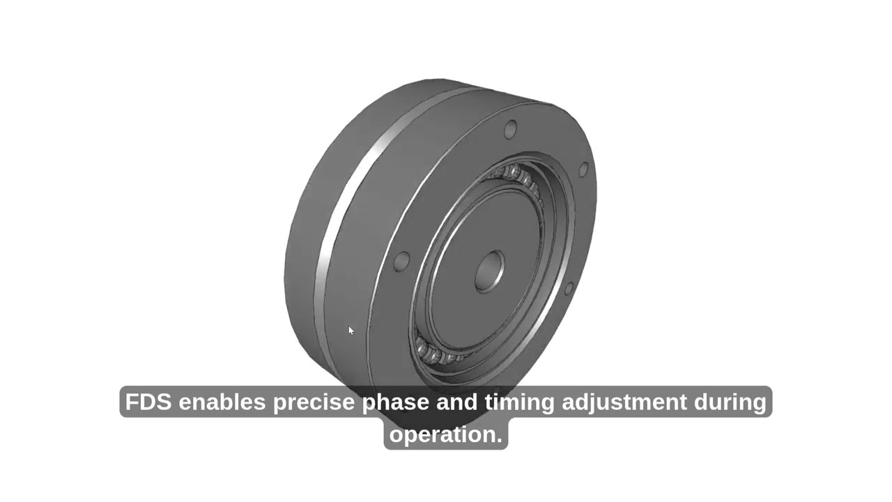
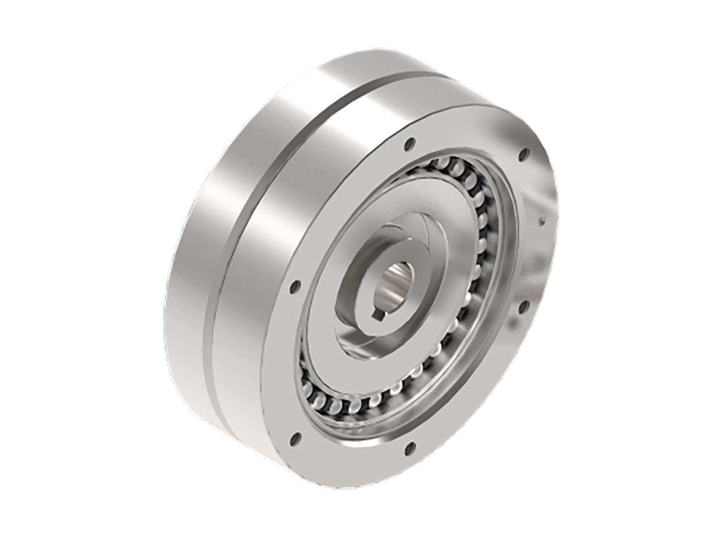
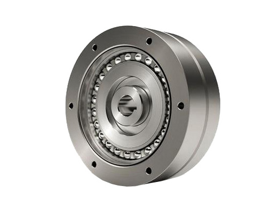
Utilizing Harmonic Drive's unique operating principle, it is an ultra-compact differential device capable of performing phase and timing fine-tuning during operation.
The combined type of the FDS series shares the same four core components as the pancake component type, except that the combined type includes additional front and rear sealing flanges and support bearings. The FDS series operates on the same working principle as the cup-type FSG series. The shape of the pancake flexspline is identical to the cross-section of the cup flexspline's base, and the wave generator bearings are arranged in two rows, with the tooth width of the circular spline and flexspline increased to handle higher torque capacity. Additionally, the pancake type incorporates an extra circular spline with the same number of teeth as the flexspline for connection to the output shaft.
Features
● This harmonic drive features a low-profile, flat and slim design with compact dimensions
● Delivers high torque output capability
● Provides excellent rotational and positioning accuracy
● Coaxial input/output shaft alignment
● The high reduction ratio between adjustment shaft and output shaft enables precise micro-adjustments while requiring minimal adjustment torque
● Commonly used for phase adjustment of rollers in color printing machinery
Specification
Sheet 1
FAQ
What Is a Double Flexspline Harmonic Reducer?
A double flexspline harmonic reducer is a harmonic transmission design that uses two coaxially arranged flexible gear elements with different tooth counts. Compared with a conventional harmonic reducer architecture that uses a rigid circular spline and a flexspline, this design introduces a stronger flexspline structure and a weaker flexspline structure that work together with the wave generator.
During operation, the wave generator causes the weak flexspline to undergo non-circular elastic deformation and partially engage with the strong flexspline. At the same time, the radial force generated at the meshing area can cause the strong flexspline to produce controlled elastic deformation.
This dual-flexible-element design creates a different harmonic transmission architecture for applications requiring compact dimensions, precision transmission and specialized motion characteristics.
How Is a Double Flexspline Harmonic Drive Different From a Conventional Harmonic Reducer?
The main difference is the transmission structure.
A conventional harmonic reducer typically uses a flexspline, a circular spline and a wave generator. The circular spline is generally treated as a relatively rigid component.
In a double flexspline harmonic reducer, the traditional rigid circular spline concept is replaced by a stronger flexspline structure that still has a flexible thin-wall section. As a result, both meshing components can participate in controlled elastic deformation during operation.
This design allows engineers to evaluate a different balance between compact structure, transmission behavior and mechanical flexibility.
Why Does the Strong Flexspline Need a Flexible Thin-Wall Structure?
The strong flexspline is stronger and more rigid than the weak flexspline, but it is not completely rigid like a conventional circular spline.
A key feature of the strong flexspline is the flexible thin-wall section located between the deformable toothed ring and the non-deformable mounting flange structure.
This thin-wall structure allows the strong flexspline to undergo controlled elastic deformation under the radial force generated by the meshing interaction with the weak flexspline.
The design therefore maintains the ability to transmit motion through precise gear engagement while allowing the two flexible gear elements to work as part of the complete harmonic transmission mechanism.
What Are the Main Advantages of a Double Flexspline Harmonic Reducer?
A double flexspline harmonic reducer can provide several engineering advantages depending on the application and specific design.
The transmission structure can support compact integration, coaxial input and output arrangements and precision motion transmission. The flexible interaction between the two gear elements also creates an alternative harmonic transmission architecture for specialized motion systems.
For equipment manufacturers, the most important advantage is not simply a single performance parameter. The value of the design lies in how the transmission structure can be matched with requirements for installation space, torque, precision, stiffness and mechanical integration.
Can a Double Flexspline Harmonic Reducer Be Used in Compact Equipment?
Yes. Compact equipment is one of the applications where this type of harmonic transmission architecture can be particularly valuable.
By integrating the transmission components into a compact coaxial structure, engineers can reduce the complexity of the external transmission chain.
This can be useful in robotics, precision automation equipment, specialized machinery and other systems where installation space is limited.
The actual suitability depends on the required torque, reduction ratio, load condition, installation structure and motion profile.
Does a Double Flexspline Harmonic Reducer Provide High Positioning Accuracy?
Positioning performance depends on the complete motion system rather than the reducer alone.
The harmonic transmission structure can support high-precision rotary motion, but the final positioning accuracy is also influenced by factors such as transmission error, torsional stiffness, encoder feedback, bearing support, load inertia, control parameters and the external mechanical structure.
For applications requiring high positioning performance, the reducer should therefore be evaluated as part of the complete actuator and machine system.
Is the Double Flexspline Harmonic Reducer Suitable for High-Torque Applications?
The suitability for high-torque applications depends on the specific model and mechanical design.
The torque capacity of a harmonic reducer is influenced by factors including gear geometry, tooth engagement, material properties, bearing support, heat generation, operating speed and duty cycle.
For high-load applications, engineers should provide the required continuous torque, peak torque, load inertia and operating conditions so that the appropriate HONPINE double flexspline harmonic reducer configuration can be evaluated.
What Information Is Needed to Select the Right Double Flexspline Harmonic Reducer?
For preliminary selection, engineers should provide the required output torque, operating speed, reduction ratio and available installation dimensions.
It is also important to understand the load inertia, radial load, axial load, overturning moment, required positioning performance and expected duty cycle.
For specialized equipment, the mounting configuration and surrounding mechanical structure should also be considered.
Providing these application parameters allows the reducer to be evaluated according to the complete motion requirement rather than only one specification.
Can HONPINE Provide Application-Specific Harmonic Reducer Solutions?
Yes. Different applications can require different combinations of torque capacity, compact dimensions, reduction ratio, stiffness, positioning performance and installation structure.
For this reason, application requirements should be evaluated before selecting the final harmonic reducer configuration.
HONPINE can work with customers to evaluate the mechanical and motion requirements of the application and help identify a suitable harmonic transmission solution.
What Applications Are Suitable for a Double Flexspline Harmonic Drive?
A double flexspline harmonic drive can be considered for robotics, precision automation equipment, specialized machinery and other compact motion systems requiring coaxial transmission and precise rotary motion.
Potential applications may include robot joints, precision positioning equipment, automated machinery, compact transmission systems and customized mechanical equipment.
The final application suitability depends on the required torque, speed, load condition, motion profile and mechanical installation requirements.
Download(3D /PDF)