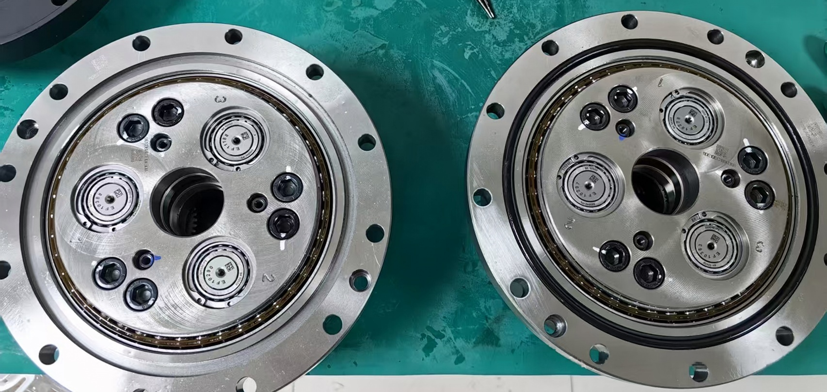









Direct Drive Motor Sizing: A Complete Guide to Torque Calculation and Selection
Selecting a direct drive motor for a precision rotary system requires more than matching the motor torque to the equipment weight. The motor must be sized according to the complete load profile, including gravity torque, inertial torque, wind torque, friction torque, rotational speed, acceleration, duty cycle, and positioning requirements.
I’m Theodore Li, Technical Director at HONPINE. In this article, I will use an azimuth and elevation turntable application as an engineering example to explain how to calculate direct drive motor torque and how these calculations can be used to guide motor selection.
The example covers the complete process from load analysis to continuous and peak torque calculation. It also explains when a frameless direct drive motor may be suitable for an integrated rotary mechanism.
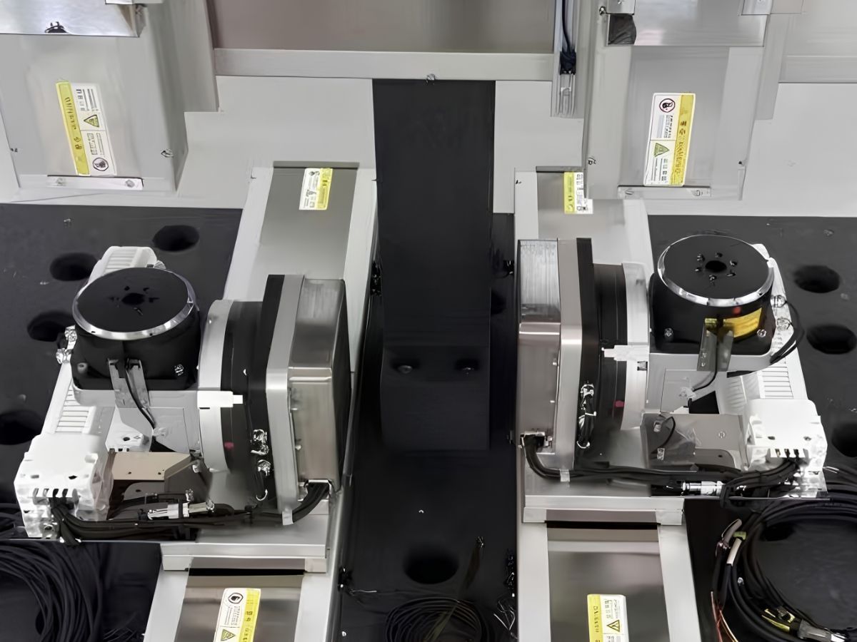
1. What Is Direct Drive Motor Sizing?
A direct drive motor is connected directly to the driven rotary mechanism without a mechanical gearbox between the motor and the load.
This architecture eliminates the need for a reduction ratio to convert motor speed into output torque. As a result, the motor directly produces the torque required at the load side.
This can provide advantages for precision rotary applications, including reduced mechanical transmission components, no gearbox backlash, direct torque transmission, and fast dynamic response.
However, direct coupling also means that the motor must directly accelerate the load inertia.
For this reason, direct drive motor sizing should begin with the actual mechanical load rather than simply selecting a motor based on rated power or equipment weight.
For a rotary axis, the required torque can generally be divided into several components:
Gravity torque
Inertial torque
Wind torque
Friction torque
The continuous torque requirement can be estimated as:
Continuous Torque = Gravity Torque + Wind Torque + Friction Torque
The peak torque requirement during acceleration can be estimated as:
Peak Torque = Gravity Torque + Wind Torque + Friction Torque + Inertial Torque
These calculations provide the mechanical load requirements that can then be compared with the direct drive motor's continuous torque, peak torque, speed, thermal capacity, and other specifications.
2. What Parameters Should Be Checked Before Selecting a Direct Drive Motor?
Before selecting a direct drive motor, engineers should establish the main operating and mechanical parameters of the rotary system.
For the turntable application discussed in this article, the relevant parameters include:
The final motor selection should also include maximum rotational speed, operating cycle, required positioning accuracy, encoder resolution, installation dimensions, bearing load, ambient temperature, and cooling conditions.
The more accurately these parameters are defined, the more reliable the direct drive motor sizing result will be.
3. How to Calculate Gravity Torque for a Direct Drive Motor?
Gravity torque becomes important when the center of gravity of the rotating assembly does not coincide with the rotational axis.
This is particularly relevant to elevation mechanisms, antenna platforms, optical systems, and other rotating structures where the payload is mounted away from the axis.
The basic calculation is:
Gravity Torque = Mass × Gravitational Acceleration × Eccentric Distance
For example, if the rotating mass is 40 kg and the center of gravity is 0.05 m from the elevation axis:
Gravity Torque = 40 × 9.8 × 0.05 = 19.6 N·m
Therefore, the elevation motor needs to overcome approximately 19.6 N·m of gravity torque under the corresponding unfavorable orientation.
This calculation demonstrates why payload mass alone is not sufficient for direct drive motor selection. Two systems with the same mass can require very different motor torque if their centers of gravity are located at different distances from the rotational axis.
For an elevation axis, the effective gravity torque also changes with angular position. The final design should therefore evaluate the complete operating range rather than relying on a single nominal position.
4. How to Calculate Inertial Torque?
Inertial torque is the torque required to accelerate or decelerate a rotating mass.
The basic relationship is:
Inertial Torque = Rotational Inertia × Angular Acceleration
For the elevation axis in this example:
Rotational Inertia = 1.6 kg·m²
Angular Acceleration = 20 rad/s²
Therefore:
Inertial Torque = 1.6 × 20 = 32 N·m
The elevation axis requires approximately 32 N·m of inertial torque during acceleration.
For the azimuth axis, the rotational inertia is approximately 3.8–3.9 kg·m².
Using 3.9 kg·m² as a representative value:
Inertial Torque = 3.9 × 20 = 78 N·m
This shows that the inertial torque of the azimuth axis can be substantially higher than the gravity torque of the elevation axis.
This is one of the most important considerations in direct drive motor sizing.
Because the motor is directly coupled to the load, the motor must accelerate the load-side inertia without relying on a gearbox to transform the mechanical motion.
5. Why Does Rotational Inertia Matter So Much in Direct Drive Applications?
A common mistake in motor selection is to focus primarily on the static weight of the equipment.
For a rotary system, however, the distribution of mass is often just as important as the total mass.
Rotational inertia depends on how far the mass is distributed from the rotational axis. A relatively lightweight structure with a large radius can therefore require substantial acceleration torque.
The acceleration torque also increases directly with angular acceleration.
For example, if the same 3.9 kg·m² azimuth assembly is accelerated at 20 rad/s², the inertial torque is approximately 78 N·m. If the required angular acceleration increases, the inertial torque increases proportionally.
This relationship makes acceleration one of the most important parameters when selecting a direct drive motor for high-dynamic rotary applications.
Engineers should therefore consider:
Total rotational inertia
Mass distribution
Angular acceleration
Acceleration time
Required speed
Motor rotor inertia
Peak torque duration
The complete motion profile is more informative than the equipment's static weight alone.
6. How to Calculate Wind Torque for a Direct Drive Motor?
For outdoor rotary equipment, wind can create an external torque that the motor must overcome.
This is especially relevant to antenna systems, tracking platforms, electro-optical equipment, radar-related mechanisms, and other exposed rotary structures.
The basic calculation can be expressed as:
Wind Force = Dynamic Pressure × Aerodynamic Coefficient × Projected Area
The corresponding torque is:
Wind Torque = Wind Force × Effective Moment Arm
Therefore:
Wind Torque = Dynamic Pressure × Aerodynamic Coefficient × Projected Area × Effective Moment Arm
The preliminary turntable data provides the following representative values:
*The supplied values are consistent with a wind-speed calculation of approximately 12 m/s. If 17.1 m/s is confirmed as the final design wind speed, the wind torque should be recalculated accordingly.
Wind pressure is proportional to the square of wind speed:
Dynamic Pressure = 0.5 × Air Density × Wind Speed²
Therefore:
Wind Torque ∝ Wind Speed²
This means that an increase in design wind speed can have a significant effect on the required motor torque.
For a final direct drive motor selection, the design wind speed, air density, projected area, aerodynamic coefficient, and effective moment arm should all be confirmed.
7. How Much Friction Torque Should Be Included?
Bearing and seal friction also contribute to the total torque requirement.
For the preliminary calculation, bearing friction torque can be estimated as:
Bearing Friction Torque = Friction Coefficient × Bearing Load × Bearing Center Diameter ÷ 2
Using a friction coefficient of 0.0015 and including an estimated seal friction torque of approximately 0.1 N·m per axis, the preliminary results are:
Compared with the inertial torque in this application, friction torque is relatively small.
However, friction should still be included in the continuous torque calculation.
For precision rotary motion, friction can also influence low-speed smoothness, servo tuning, tracking performance, and positioning stability. Therefore, friction is both a mechanical load parameter and a motion-control consideration.
8. How to Calculate Continuous Torque?
Continuous torque represents the torque required to maintain the required motion under sustained operating conditions.
For the turntable example:
Continuous Torque = Gravity Torque + Wind Torque + Friction Torque
For the elevation axis:
Continuous Torque = 19.60 + 0.56 + 0.27 = 20.43 N·m
For the azimuth axis, based on the supplied preliminary values:
Continuous Torque = 0 + 2.23 + 0.62 = 2.85 N·m
The resulting values are:
The difference between the two axes is significant.
The elevation axis is primarily affected by the eccentric gravity load, while the azimuth axis has a relatively small continuous external torque requirement under the supplied conditions.
9. How to Calculate Peak Torque?
Peak torque becomes particularly important during acceleration and deceleration.
The basic calculation is:
Peak Torque = Gravity Torque + Wind Torque + Friction Torque + Inertial Torque
For the elevation axis:
Peak Torque = 19.60 + 0.56 + 0.27 + 32.00
Peak Torque = 52.43 N·m
For the azimuth axis, using the supplied representative inertial torque of approximately 79.60 N·m:
Peak Torque = 2.23 + 0.62 + 79.60
Peak Torque ≈ 82.45 N·m
The preliminary results are therefore:
This calculation reveals an important characteristic of the application:
The elevation axis is primarily limited by gravity torque during continuous operation, while the azimuth axis is primarily affected by inertial torque during acceleration.
Therefore, the two axes should not necessarily use the same direct drive motor sizing strategy.
10. What Is the Difference Between Continuous Torque and Peak Torque?
Continuous torque and peak torque describe different operating requirements.
Continuous torque is the torque the motor must provide for sustained operation without exceeding its allowable thermal operating condition.
Peak torque is the higher torque required for a limited period, typically during acceleration, deceleration, rapid positioning, or temporary external load changes.
A direct drive motor should therefore be evaluated against both values.
For example, a motor may provide sufficient peak torque to accelerate a high-inertia load but still be unsuitable if its continuous torque or thermal capacity is insufficient for sustained operation.
Conversely, selecting a motor solely according to continuous torque may result in insufficient acceleration performance.
The motor's continuous torque, peak torque, peak torque duration, speed, current, and thermal behavior should therefore be evaluated together with the actual motion profile.
11. How to Select a Direct Drive Motor After Calculating Torque?
The calculated load torque provides the starting point for motor selection, but it does not define the complete motor specification.
For the example turntable, the preliminary mechanical requirements are:
Elevation Axis
Continuous load torque: 20.43 N·m
Peak load torque: 52.43 N·m
Azimuth Axis
Continuous load torque: 2.85 N·m
Peak load torque: approximately 82.45 N·m
These values represent the calculated load requirements rather than the final motor rating.
The selected direct drive motor should provide sufficient engineering margin according to the application.
The selection should also consider:
The final motor should therefore be selected from the complete load and motion profile rather than from torque alone.
12. Direct Drive Motor Sizing Checklist
Before requesting or selecting a direct drive motor, engineers can prepare the following information:
Providing these parameters at the beginning of the motor selection process can significantly reduce repeated calculations and help determine whether a standard direct drive motor or a customized mechanical integration is appropriate.
Direct Drive Motor vs. Geared Motor
Direct drive motors and geared motor systems use fundamentally different transmission architectures.
A geared motor can provide substantial output torque through mechanical reduction, which can be useful for many applications.
A direct drive motor, on the other hand, can be advantageous when the application places a high value on direct torque transmission, low mechanical backlash, fast dynamic response, smooth low-speed movement, or simplified rotary transmission.
The appropriate architecture should be determined by the complete application requirements.
When Should You Consider a Frameless Direct Drive Motor?
For applications requiring deeper mechanical integration, a frameless direct drive motor can be an alternative to a conventional housed motor.
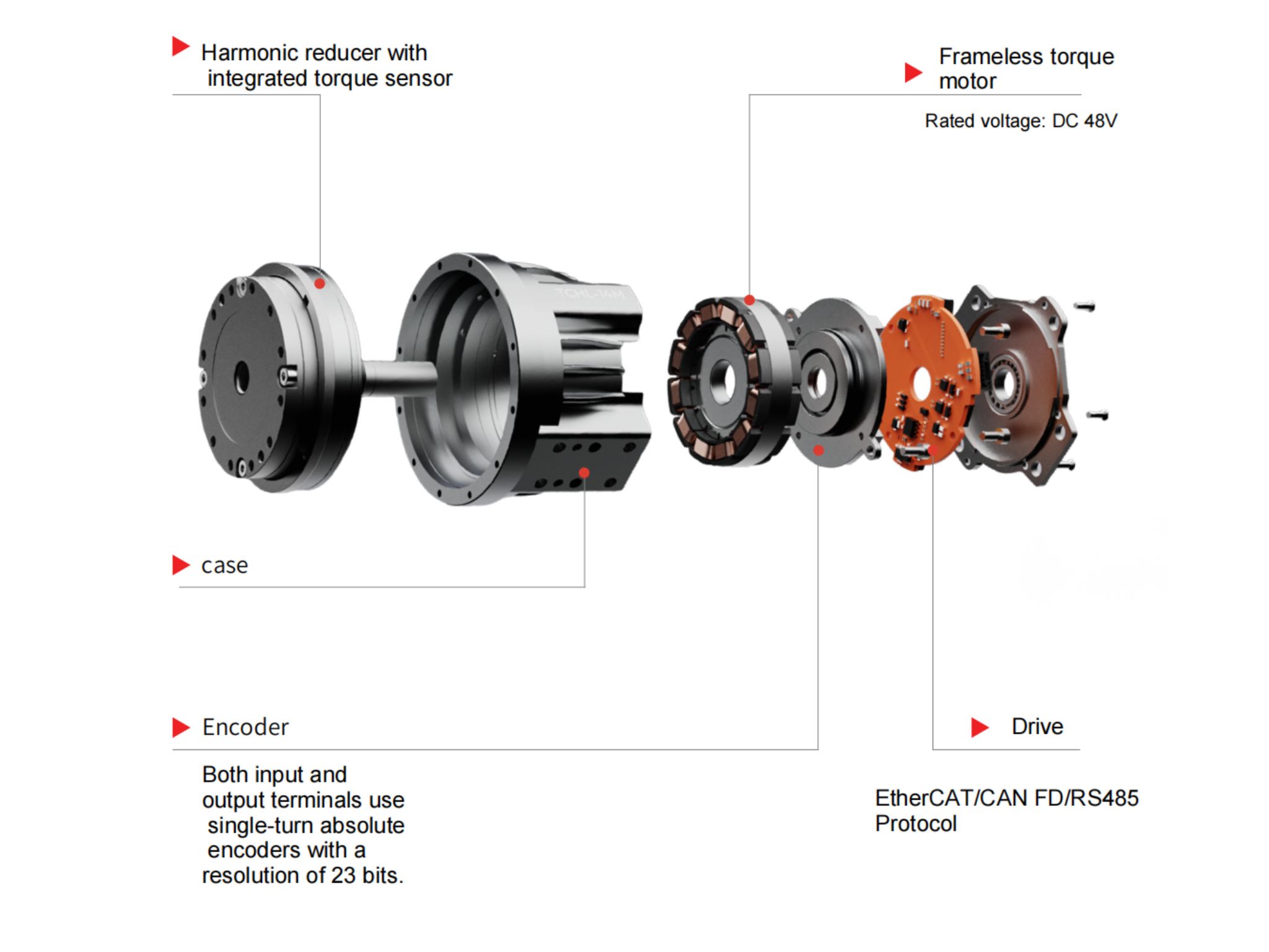
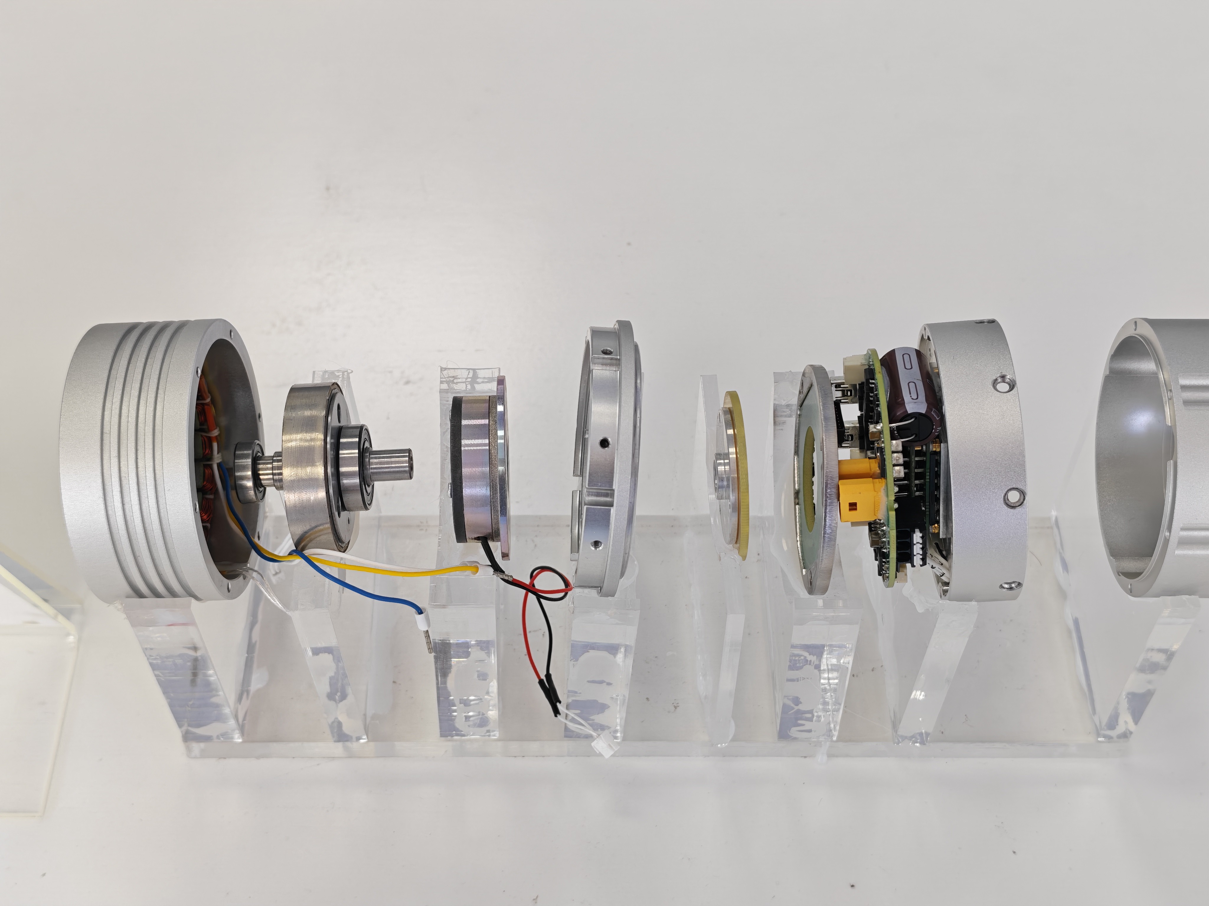
A typical frameless direct drive motor consists primarily of a stator and rotor.
The customer or system integrator can integrate the motor with:
Bearings
Mechanical housing
Encoder
Shaft or rotary structure
Cooling system
Cable routing
Brake, when required
This approach allows the motor to become part of the machine's rotary mechanism rather than functioning as a separate motor package.
For azimuth and elevation mechanisms, tracking platforms, robotic joints, rotary tables, and other precision rotary systems, a frameless direct drive motor can provide greater flexibility in mechanical packaging.
However, frameless motor selection requires system-level evaluation.
The motor should be evaluated together with the bearing structure, rotor support, encoder installation, mechanical rigidity, thermal dissipation, and available installation space.
How Should a Direct Drive Motor Be Validated?
Torque calculation is an important first step, but the final motor selection should be validated against the complete operating condition.
A practical validation process can include:
1. Load calculation
Confirm the actual mass, center of gravity, rotational inertia, friction, wind load, and other external loads.
2. Motion profile
Confirm maximum speed, acceleration, deceleration, positioning frequency, and duty cycle.
3. Motor selection
Check continuous torque, peak torque, speed, current, rotor inertia, encoder, thermal capacity, and mechanical dimensions.
4. Servo simulation or calculation
Evaluate whether the motor can achieve the required acceleration and positioning response.
5. Prototype testing
Where appropriate, test the motor under representative load and operating conditions.
6. Thermal validation
Confirm motor temperature and continuous torque capability under the actual duty cycle.
7. Final system validation
Verify positioning accuracy, tracking performance, acceleration response, stability, and environmental performance.
This process is particularly important when the direct drive motor is used in a precision rotary mechanism where the motor, bearing, encoder, and mechanical structure operate as one system.
Key Takeaways for Direct Drive Motor Sizing
The turntable case demonstrates several important principles.
Static load is not enough for motor sizing.
The direct drive motor must overcome gravity, inertia, wind, and friction.
Rotational inertia can determine peak torque.
For the example azimuth axis, a rotational inertia of approximately 3.9 kg·m² and an angular acceleration of 20 rad/s² produce approximately 78 N·m of inertial torque.
Eccentricity can determine continuous torque.
A 40 kg rotating mass with a 0.05 m eccentric distance produces approximately 19.6 N·m of gravity torque.
Continuous and peak torque must be evaluated separately.
A motor with sufficient peak torque may still be unsuitable if its continuous torque or thermal capacity is insufficient.
Torque is only one part of direct drive motor selection.
Speed, inertia, encoder feedback, thermal performance, bearing capacity, installation dimensions, control requirements, and duty cycle should also be considered.
Conclusion
Direct drive motor sizing for an azimuth and elevation turntable is a system-level engineering problem involving both torque and motion requirements.
For the preliminary turntable example discussed in this article, the calculated load requirements are:
These values provide a starting point for direct drive motor selection.
Before finalizing the motor specification, the actual mechanical structure, mass distribution, rotational inertia, design wind speed, maximum speed, acceleration profile, duty cycle, thermal conditions, and required positioning performance should be confirmed.
For applications requiring direct torque transmission and precision rotary motion, HONPINE can evaluate direct drive motor requirements based on load torque, rotational inertia, speed, acceleration, encoder requirements, installation constraints, and operating conditions.
If you are selecting a direct drive motor for an antenna turntable, azimuth/elevation mechanism, rotary platform, tracking system, robotic joint, or other precision rotary application, providing the load mass, rotational inertia, eccentric distance, speed, acceleration, and duty cycle is a practical starting point for determining the required continuous and peak torque.

About Author
Theodore Li serves as the Technical Director at HONPINE, overseeing the R&D strategy for replication products, guiding team selection, and managing both pre-sales and after-sales operations.

Read More
Learn more about the story of HONPINE and industry trends related to precision transmission.
 What is robot joint actuator?How to Choose the Best Robot Rotary Joint Actuator?In core robot joint transmission solutions, planetary and harmonic rotary actuators each have their own strengths. Choosing the right type based on application requirements is essential to achieve the optimal balance between performance and cost.
 DD Motors VS Harmonic Rotary ActuatorsThis article provides an in-depth comparison between Direct Drive (DD) motors and harmonic rotary actuators, covering their transmission principles, advantages and disadvantages, and typical application fields.
 OMG Ultra Compact Harmonic Drive Joint Module with Built-in Torque SensorHONPINE TCHL series harmonic drive joint module is a game-changing product that achieves disruptive improvements in multiple aspects such as lightweight design, integration level, and connection convenience. This article will analyze its revolutionary enhancements with you.
 The Role of Harmonic Drive Gears in Achieving 5–10 μm Accuracy in Dental Milling MachinesA dental milling machine is a CNC machining system used to directly process digital dental models into restorations such as crowns, bridges, veneers, inlays, and implant abutments. Dental milling machines require far higher operational accuracy and motion stability than ordinary equipment. This article explains how harmonic drive gear help dental milling machines achieve stable, continuous, and controllable operation.
 Why Are Harmonic Rotary Actuators Perfect for Medical Equipment?Harmonic rotary actuators (typically integrated systems consisting of a harmonic drive reducer, frameless torque motor, encoder, and optional brake) are regarded as key components in medical equipment. The core reason is that they simultaneously meet the most stringent medical requirements for precision, compact size, safety, and controllability. The following explanation is structured from three perspectives: technical characteristics, application scenarios, and medical value.
 High-Precision RV Reducers Perfectly Matched for Walking RobotsThe walking axis of a robot is a core component for power transmission and support. RV reducers provide extremely high rigidity, precision, and torque while maintaining a compact size and exceptional reliability, making them an ideal match for the demanding requirements of walking robot joints in terms of load capacity, impact resistance, and precision.
 Does a Higher Gearbox Ratio Mean More Torque? Planetary, Harmonic, and RV Gearboxes ExplainedDoes a higher gearbox ratio mean more torque? This engineering guide explains the relationship between gearbox ratio, output torque, and output speed, and compares planetary gearboxes, harmonic gearboxes, and RV gearboxes. Learn why reduction ratio alone cannot determine gearbox torque capacity, efficiency, dynamic response, precision, or service life, and what engineers should consider when selecting a gearbox for robotics, CNC machines, servo systems, and industrial motion control.
 High-Precision Hollow Harmonic Rotary Actuator for CNC Machines and Heavy-Duty Rotary AxesHONPINE 58 Series Hollow Harmonic Rotary Actuator is designed for CNC rotary tables, precision rotary axes, laser processing equipment, and heavy-duty rotary positioning applications. With a 50 mm hollow bore, up to 2,722 N·m peak torque, integrated crossed roller bearing, multi-turn absolute encoder options, positioning accuracy below 30 arcsec, and repeat positioning accuracy below 5 arcsec, it combines high torque capacity with precision rotary motion and flexible mechanical integration.
 How Does the HONPINE JRM Planetary Robot Joint Module Address Temperature Rise in Continuous Operation?HONPINE JRM planetary robot joint modules are designed for long-duration and high-load robotic operation. This article examines how motor electromagnetic optimization, high-efficiency planetary transmission, GaN-based drive technology, and system-level low-loss design help control temperature rise. Using the C6345 planetary robot joint module as a test example, HONPINE also presents full-load thermal validation under continuous operation, including motor efficiency up to 92%, planetary gearbox efficiency up to 97%, and a final equilibrium temperature of 61.42°C at a 25°C ambient temperature.
 Direct Drive Motor Sizing: A Complete Guide to Torque Calculation and SelectionSelecting a direct drive motor for a precision rotary system requires more than matching motor torque to the equipment weight. Engineers need to evaluate gravity torque, inertial torque, wind torque, friction, rotational inertia, speed, acceleration, duty cycle, and positioning requirements. In this guide, Theodore Li, Technical Director at HONPINE, explains a practical approach to direct drive motor sizing and torque calculation using an azimuth and elevation turntable as an engineering example. The article covers continuous and peak torque calculation, motor selection criteria, and the application of frameless direct drive motors in integrated rotary systems.
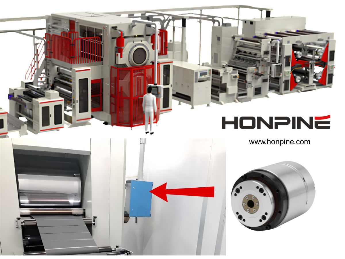
 Harmonic Rotary Actuator for Lithium Battery Roller Press EquipmentLithium battery manufacturing equipment requires higher precision, stability, and integration efficiency as production processes continue to evolve. In roller press equipment, accurate roller positioning, pressure control, and dynamic response are critical for ensuring electrode quality and consistency.
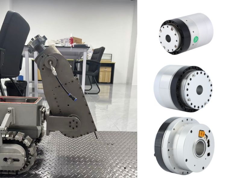
HONPINE harmonic rotary actuators provide high precision, high rigidity, fast response, and compact integration for lithium battery roller press equipment. With near-zero backlash, high torque density, and reliable motion control performance, they help improve equipment accuracy and production stability. Harmonic Robot Joint Actuators for Pipeline Robots and Other Special-Purpose EquipmentPipeline robots operate in narrow and complex environments where limited installation space, high load requirements, cable routing, and precise motion control are critical challenges. A reliable joint actuator must provide high torque output, compact dimensions, and stable performance while adapting to demanding operating conditions. Harmonic robot joint actuators integrate precision transmission, motor drive, and sensing capabilities into a compact motion unit, making them suitable for pipeline robots and other special-purpose robotic systems. This article explores the key design requirements of pipeline robots and explains how HONPINE HPJM harmonic robot joint modules help achieve compact, high-performance, and reliable robotic solutions.
Double Click
We provide harmonic drive reducer,planetary reducer,robot joint motor,robot rotary actuators,RV gear reducer,robot end effector,dexterous robot hand
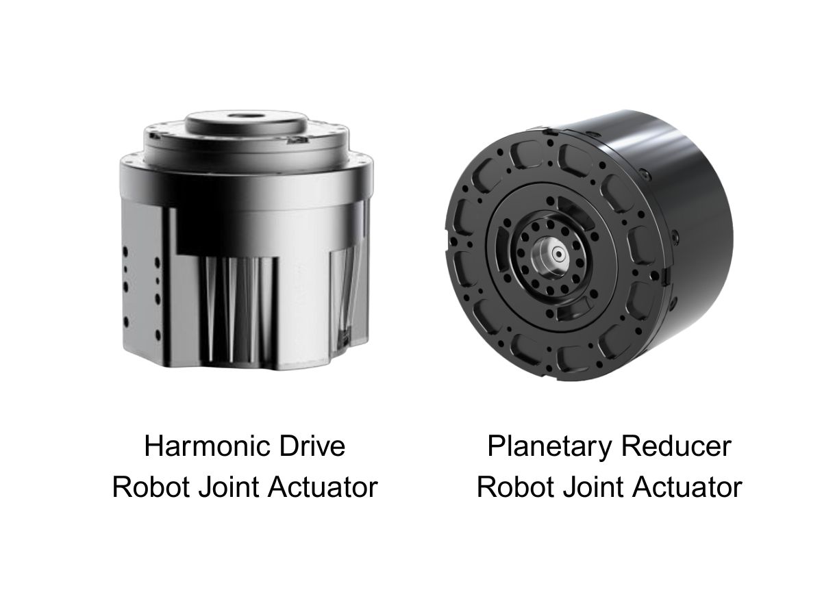
 What is robot joint actuator?How to Choose the Best Robot Rotary Joint Actuator?In core robot joint transmission solutions, planetary and harmonic rotary actuators each have their own strengths. Choosing the right type based on application requirements is essential to achieve the optimal balance between performance and cost.
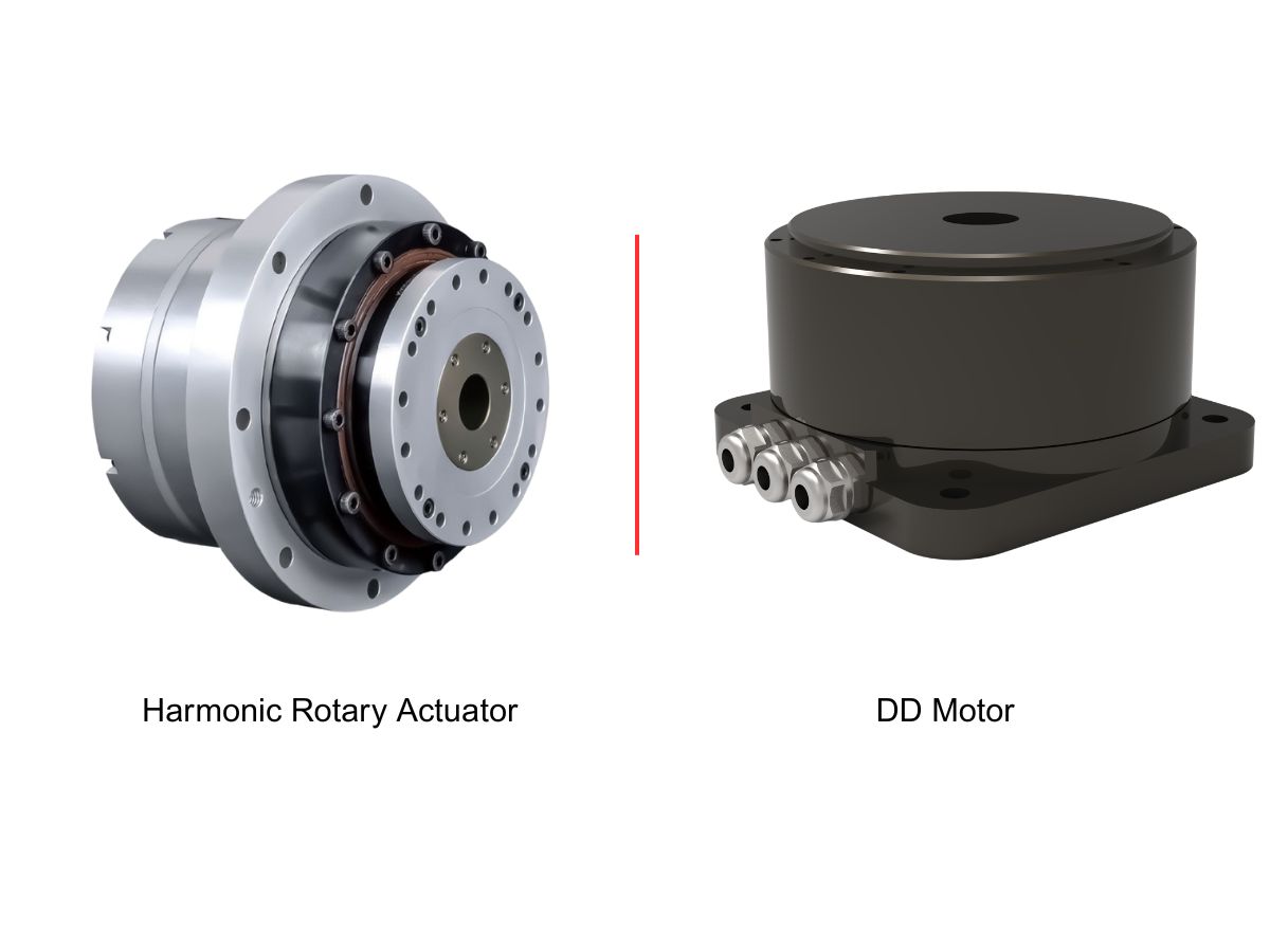
 DD Motors VS Harmonic Rotary ActuatorsThis article provides an in-depth comparison between Direct Drive (DD) motors and harmonic rotary actuators, covering their transmission principles, advantages and disadvantages, and typical application fields.
 OMG Ultra Compact Harmonic Drive Joint Module with Built-in Torque SensorHONPINE TCHL series harmonic drive joint module is a game-changing product that achieves disruptive improvements in multiple aspects such as lightweight design, integration level, and connection convenience. This article will analyze its revolutionary enhancements with you.
 Does a Higher Gearbox Ratio Mean More Torque? Planetary, Harmonic, and RV Gearboxes ExplainedDoes a higher gearbox ratio mean more torque? This engineering guide explains the relationship between gearbox ratio, output torque, and output speed, and compares planetary gearboxes, harmonic gearboxes, and RV gearboxes. Learn why reduction ratio alone cannot determine gearbox torque capacity, efficiency, dynamic response, precision, or service life, and what engineers should consider when selecting a gearbox for robotics, CNC machines, servo systems, and industrial motion control.
 High-Precision Hollow Harmonic Rotary Actuator for CNC Machines and Heavy-Duty Rotary AxesHONPINE 58 Series Hollow Harmonic Rotary Actuator is designed for CNC rotary tables, precision rotary axes, laser processing equipment, and heavy-duty rotary positioning applications. With a 50 mm hollow bore, up to 2,722 N·m peak torque, integrated crossed roller bearing, multi-turn absolute encoder options, positioning accuracy below 30 arcsec, and repeat positioning accuracy below 5 arcsec, it combines high torque capacity with precision rotary motion and flexible mechanical integration.
 How Does the HONPINE JRM Planetary Robot Joint Module Address Temperature Rise in Continuous Operation?HONPINE JRM planetary robot joint modules are designed for long-duration and high-load robotic operation. This article examines how motor electromagnetic optimization, high-efficiency planetary transmission, GaN-based drive technology, and system-level low-loss design help control temperature rise. Using the C6345 planetary robot joint module as a test example, HONPINE also presents full-load thermal validation under continuous operation, including motor efficiency up to 92%, planetary gearbox efficiency up to 97%, and a final equilibrium temperature of 61.42°C at a 25°C ambient temperature.
 Direct Drive Motor Sizing: A Complete Guide to Torque Calculation and SelectionSelecting a direct drive motor for a precision rotary system requires more than matching motor torque to the equipment weight. Engineers need to evaluate gravity torque, inertial torque, wind torque, friction, rotational inertia, speed, acceleration, duty cycle, and positioning requirements. In this guide, Theodore Li, Technical Director at HONPINE, explains a practical approach to direct drive motor sizing and torque calculation using an azimuth and elevation turntable as an engineering example. The article covers continuous and peak torque calculation, motor selection criteria, and the application of frameless direct drive motors in integrated rotary systems.
 How Integrated Robot Joint Modules Are Reshaping Robot Wiring and Control Architecture?Integrated robot joint modules are changing how robots are designed by combining the motor, reducer, drive, encoder, and sensing components into a compact motion unit. Compared with traditional distributed architectures, this integrated approach can reduce cable complexity, simplify power and communication connections, and support more compact robot structures. As humanoid robots demand higher levels of motion coordination, response speed, precision, and integration, robot joint modules are becoming an increasingly important interface between intelligent control systems and physical movement. This article explains how integrated robot joint modules reshape robot wiring and control architecture, using the HONPINE TCHL harmonic drive robot joint module as an example.
 Force-Controlled Harmonic Joint Modules: A Key Solution for Robot CommercializationAs robots move from precise positioning toward physical interaction, joint-level torque feedback is becoming increasingly important. A force-controlled robot joint module allows the robot to sense changes in output torque and respond more appropriately to external loads, supporting compliant motion, contact detection, and force-controlled applications. HONPINE HAG and HAU harmonic joint modules integrate torque sensing directly into the joint, enabling torque closed-loop control, 360° continuous output rotation, less than 1% torque control accuracy, and a 50 Hz torque bandwidth. This integrated design also maintains consistent dimensions between force-controlled and non-force-controlled configurations, providing a flexible joint platform for robot manufacturers.
 6 Key Advantages of the HONPINE JRM Planetary Joint ModuleHigh-performance quadruped robots require joint modules that can respond quickly, maintain precise positioning, withstand repeated impacts, and deliver stable torque under demanding operating conditions. The HONPINE JRM planetary joint module combines high positioning accuracy, low backlash, fast three-loop response, high static rigidity, strong overload capability, and a wide operating temperature range. With clearly defined continuous and overload operating limits, the JRM is designed to balance dynamic performance with long-term reliability. This article introduces six key advantages of the HONPINE JRM planetary joint module and explains why it is suitable for industrial inspection quadrupeds, specialized inspection robots, explosion-proof quadruped robots, and other high-performance robotic platforms.
 Robot Joint Module Solutions for Humanoid Robot Arms and LegsHumanoid robots require different joint characteristics across the shoulder, elbow, wrist, hip, knee, and ankle. Smaller joints prioritize low weight and fast response, while larger joints require higher torque density, load capacity, and reliability. A suitable robot joint module should therefore be matched to the specific torque, weight, range of motion, and control requirements of each joint. In this article, HONPINE uses the HPJM harmonic joint module series as an example to present a joint configuration solution for humanoid robot upper and lower limbs, covering torque requirements from small wrist and finger joints to high-load hip joints.
 Why Does an RV Reducer Need Profile Modification? How to Further Reduce Backlash and Transmission Error?An RV Reducer is designed to deliver high torque, high stiffness, and precise motion for demanding applications such as robotic joints, industrial rotary tables, and precision machinery. However, achieving low backlash and stable transmission accuracy requires more than high-precision machining. Cycloidal profile modification must also account for manufacturing tolerances, assembly errors, load-induced deformation, thermal expansion, and lubrication conditions. In this article, we examine why RV reducers require profile modification, how different modification methods affect meshing, and how engineers can further control backlash and transmission error through profile design, error budgeting, structural analysis, precision manufacturing, and validation testing.