







Harmonic Drive Actuator Accuracy: Why It Should Be Evaluated at Four Levels
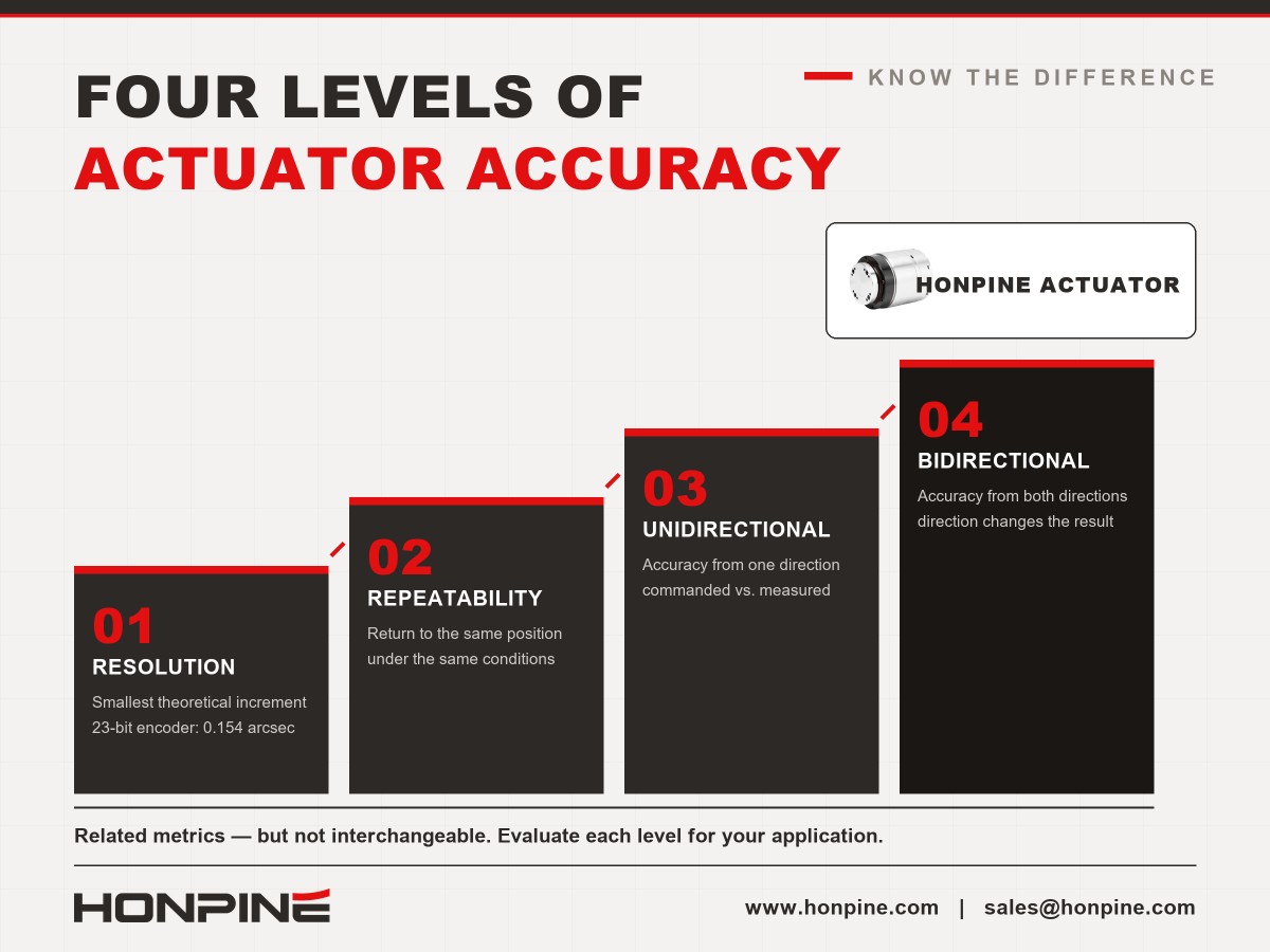
The accuracy of a harmonic drive actuator is often misunderstood because several different performance metrics are used to describe its motion. Encoder resolution, repeatability, unidirectional positioning accuracy, and bidirectional positioning accuracy are related, but they are not interchangeable.
For example, a high-resolution encoder may provide extremely fine measurement increments, but this does not mean the actuator's output shaft can achieve the same level of absolute positioning accuracy. Mechanical transmission errors, structural compliance, bearing characteristics, encoder configuration, and control parameters all influence the final result.
For engineers selecting a harmonic rotary actuator, understanding these four levels of accuracy helps prevent overestimating performance based on a single specification.
1. Resolution: How Small Is the Theoretical Measurement Increment?
Resolution describes the smallest detectable or commandable increment of a measurement or control system. In a rotary actuator, it is often associated with encoder resolution.
Consider a rotary actuator equipped with a 23-bit single-turn encoder. The encoder divides one revolution into approximately 8.39 million theoretical counts. The corresponding angular increment is approximately 0.154 arcseconds at the encoder shaft.
If this encoder is installed on the motor side of a harmonic drive actuator with a 101:1 reduction ratio, the theoretical output-side increment would be approximately 0.0015 arcseconds, assuming an ideal transmission ratio and no additional quantization or processing limitations.
These figures may look impressive, but they should not be interpreted as the actuator's actual positioning accuracy.
The encoder measures angular movement at its installation point. The complete actuator also contains mechanical components that can introduce transmission errors, elastic deformation, friction, and other deviations. The output-side encoder configuration, feedback architecture, controller, and measurement method also affect the practical result.
Key takeaway: Resolution describes the fineness of measurement or command increments. It does not independently establish the accuracy of the actuator's output position.
2. Repeatability: Can the Actuator Return to the Same Position?
Repeatability describes how closely an actuator returns to the same position when the same positioning operation is repeated under specified conditions.
For industrial automation, repeatability is often one of the most useful specifications because equipment may repeatedly perform the same motion cycle over thousands or millions of operations.
However, repeatability must be evaluated under defined test conditions. Test direction, load, speed, temperature, mounting rigidity, control settings, and the measurement method can all affect the result. It is therefore important to check how a manufacturer's stated value was measured before comparing products.
Why Repeatability Matters in Practical Applications?
Repeatability is particularly relevant to applications such as rotary indexing, repetitive inspection, dispensing, screwdriving, and component handling. If an actuator repeatedly reaches a consistent position, the machine can often compensate for a known systematic offset through calibration.
Nevertheless, good repeatability does not necessarily mean high absolute positioning accuracy. An actuator may return to nearly the same position every time while consistently stopping slightly away from the intended target.
When evaluating a specification such as ≤10 arcseconds, engineers should confirm the applicable model, operating conditions, test method, and whether the figure represents unidirectional or bidirectional repeatability.
3. Unidirectional Positioning Accuracy: How Close Is the Actual Position to the Target?
Unidirectional positioning accuracy describes the deviation between a commanded target position and the measured position when the target is approached from a specified direction.
Unlike repeatability, which evaluates consistency across repeated movements, positioning accuracy also reflects systematic deviations between the commanded and actual positions.
In a harmonic drive actuator, positioning errors can be affected by transmission characteristics, mechanical deformation, manufacturing tolerances, assembly conditions, and the control system. Periodic error components may also occur during rotation. Their magnitude and pattern depend on the specific design and operating conditions.
Can Error Compensation Improve Positioning Accuracy?
In some systems, a measured error map or compensation table can reduce repeatable systematic errors. The controller can use the measured relationship between commanded positions and actual positions to apply corrections.
However, compensation cannot automatically eliminate all positioning errors. Its effectiveness depends on the stability of the error pattern, measurement quality, controller capability, operating load, temperature, and other conditions. Errors that change with direction, load, or time may be more difficult to compensate fully.
For this reason, engineers should distinguish between a manufacturer's unidirectional positioning accuracy specification, a compensated system result, and the overall positioning performance of the finished machine.
4. Bidirectional Positioning Accuracy: Does Direction Change the Result?
Bidirectional positioning accuracy evaluates positioning performance when the target is approached from both directions. It is important in applications where the actuator frequently reverses direction or must position accurately from either side of a target.
Mechanical transmission behavior, friction, elastic deformation, and direction-dependent errors can cause the measured position to differ depending on the direction of approach. The actual impact depends on the actuator's design, control strategy, load, and test procedure.
Bidirectional positioning accuracy should not be assumed to be identical to unidirectional positioning accuracy. Engineers should check whether the published specification includes both directions and how the manufacturer defines and measures the result.
For rotary indexing, scanning, inspection, and other applications involving frequent reversals, this metric may be particularly important. Testing the actuator under representative operating conditions can help establish whether its performance meets the application's requirements.
HONPINE Harmonic Rotary Actuator Specifications
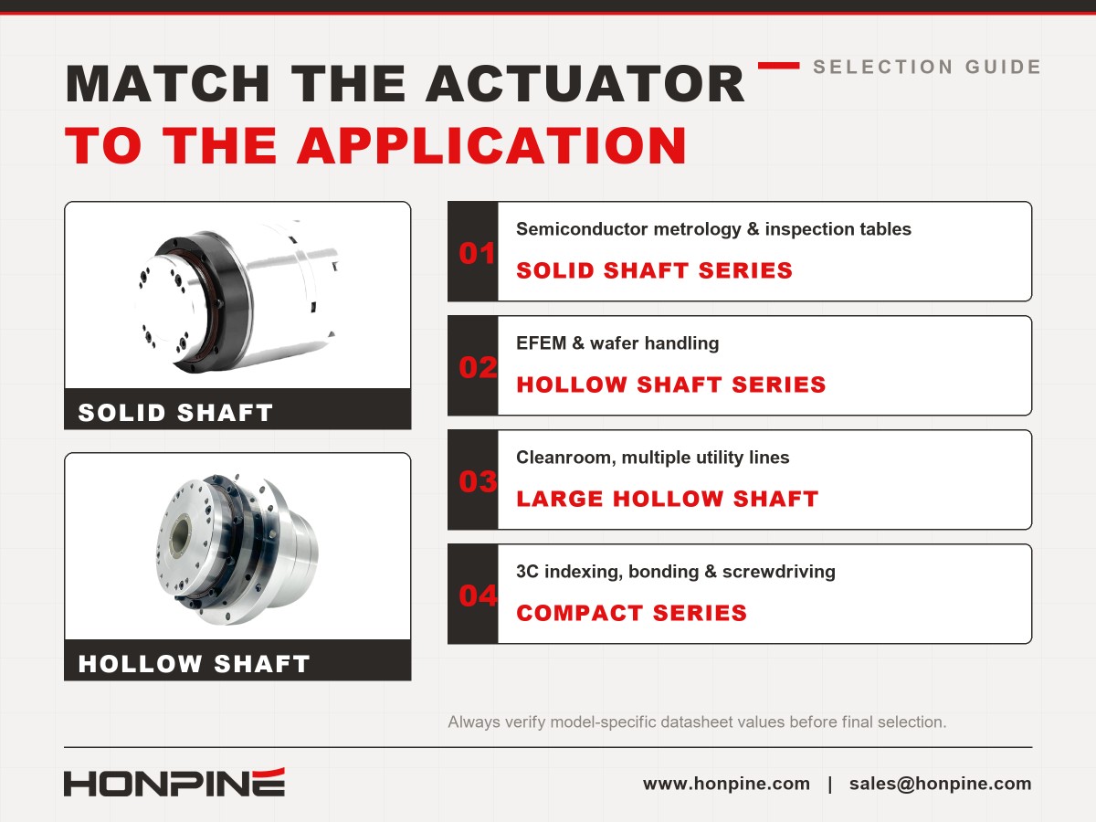
HONPINE offers external-driver harmonic rotary actuators in solid-shaft and hollow-shaft configurations. These configurations address different installation requirements, including structural support, through-axis cable routing, and integration with automation equipment.
The following table summarizes selected model ranges and their stated specifications. Exact performance depends on the model and configuration, so engineers should verify the relevant datasheet before final selection.
When comparing the specifications, do not treat repeatability and unidirectional positioning accuracy as equivalent values. They describe different performance characteristics and should be assessed against the machine's actual requirements.
Encoder resolution should also be evaluated as part of the complete feedback and control system, rather than as a substitute for measured output accuracy.
Why 10 Arcseconds Can Matter in Precision Automation?
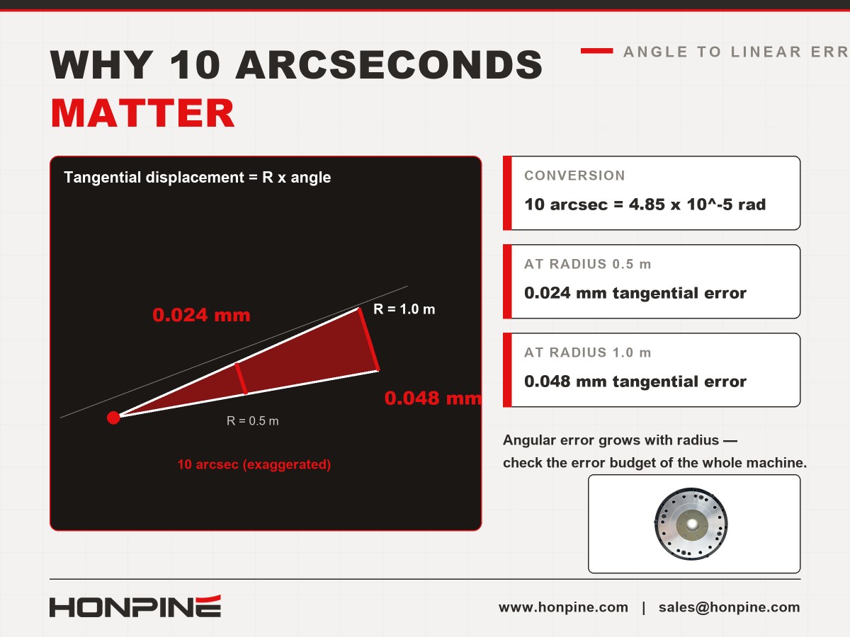
Ten arcseconds is a small angular displacement, but its practical significance depends on the distance from the axis of rotation to the point where positioning error matters.
Ten arcseconds is approximately 4.85 × 10⁻⁵ radians. For a point located 0.5 m from the rotational axis, this corresponds to a tangential displacement of approximately 0.024 mm. At a radius of 1 m, the corresponding displacement is approximately 0.048 mm.
These calculations illustrate how angular error can translate into linear displacement. They do not guarantee the accuracy of the complete machine, which may also be affected by structural deflection, mounting errors, calibration, thermal effects, and other sources of error.
Semiconductor Equipment and Metrology Applications
Semiconductor equipment can require precise rotary positioning for wafer handling, inspection, alignment, and other automated processes. In these systems, actuator performance must be considered alongside the accuracy and repeatability requirements of the complete mechanism.
For metrology and inspection rotary tables, the positioning requirement may be particularly demanding. Engineers should evaluate not only the actuator's repeatability and positioning accuracy, but also output stiffness, runout, mounting geometry, vibration, thermal stability, and the measurement system.
EFEM and Vacuum Robot Applications
Equipment front-end modules (EFEMs) and semiconductor handling systems may require compact rotary actuators that provide space for cables, vacuum lines, pneumatic lines, or other utilities.
Hollow-shaft harmonic rotary actuators can simplify routing through the axis of rotation. Depending on the model, larger through-holes may help reduce cable congestion and make equipment integration easier.
Environmental requirements should also be checked carefully. IP65 protection or a customized IP67 configuration may be relevant in some installations, but the required protection level must be confirmed for the actual actuator and its connectors. For vacuum environments, lubricant outgassing, material compatibility, and operating conditions should be reviewed with the manufacturer rather than inferred from the actuator's general specifications.
Applying Harmonic Rotary Actuators in 3C Automation
In 3C manufacturing—covering computers, communications equipment, and consumer electronics—rotary actuators may be used in indexing tables, bonding systems, dispensing equipment, screwdriving stations, and precision assembly lines.
The appropriate accuracy level depends on the process tolerance, the distance between the rotational axis and the working point, the fixture design, and the total error budget of the machine.
For example, a linear tolerance of ±0.05 mm at a radius of 0.5 m corresponds to an angular tolerance of approximately 20.6 arcseconds, if angular positioning error is the only error source. A 10-arcsecond angular error corresponds to approximately 0.024 mm of tangential displacement at the same radius.
This comparison can help engineers assess whether an actuator specification is suitable as part of the system design. It should not be interpreted as a guaranteed machine-level tolerance, because other sources of error may consume part of the available error budget.
External-driver architecture may also be useful when the drive electronics need to be installed in a control cabinet or when the machine's electrical and thermal layout favors separating the driver from the actuator. However, external-driver and integrated-driver solutions should be compared using their actual motor performance, transmission characteristics, control bandwidth, cooling conditions, installation constraints, and total system requirements. Neither architecture is inherently superior in every application.
How to Select the Right HONPINE Actuator for Your Application?
The selection process should begin with the required output performance and mechanical interface, rather than a single encoder or accuracy number.
Semiconductor Metrology and Inspection Rotary Tables
For precision rotary tables, evaluate positioning accuracy, repeatability, torsional stiffness, runout, thermal behavior, and the rigidity of the mounting structure. A solid-shaft configuration may suit designs that prioritize a particular mechanical interface or support arrangement. Confirm the selected model's specifications against the system's error budget.
EFEM and Vacuum Handling Systems
For EFEM and wafer-handling applications, a hollow-shaft actuator may help route cables and utilities through the rotational axis. Select the bore size according to the actual routing requirements, while also checking load, stiffness, positioning performance, environmental compatibility, and installation space.
Cleanroom Systems Requiring Multiple Utility Lines
When several cables, pneumatic lines, or other services must pass through the rotary axis, a large hollow-shaft configuration may simplify integration. Compare the usable through-hole diameter, actuator outer dimensions, mounting interfaces, and the available internal routing space for each specific model.
3C Rotary Indexing, Bonding, and Screwdriving
For 3C automation, choose an actuator based on the process tolerance, cycle time, payload, rotational inertia, and required repeatability. Where the process has a relatively broad tolerance, a more economical model may be sufficient. Where the working point is far from the rotational axis or the process tolerance is tight, evaluate the angular error budget carefully.
Applications Requiring Positioning Accuracy Near 5 Arcseconds
If an application requires positioning accuracy at approximately the 5-arcsecond level, do not select a transmission type based solely on a general rule. Request model-specific test data and confirm the test conditions, output measurement method, load, control configuration, and compensation strategy.
A high-precision planetary actuator or another transmission solution may be worth evaluating when its measured performance, stiffness, and dynamic characteristics better fit the application. The final decision should be based on verified specifications and system-level testing, not on transmission category alone.
Conclusion: Evaluate Accuracy as a Complete System Performance
Harmonic drive actuator accuracy should not be judged by encoder resolution alone. Resolution describes the fineness of measurement increments; repeatability describes consistency across repeated movements; unidirectional positioning accuracy describes deviation when approaching from one direction; and bidirectional positioning accuracy considers positioning from both directions.
For semiconductor equipment, EFEM systems, and 3C automation, the most appropriate actuator is the one whose verified performance matches the machine's accuracy requirements, mechanical constraints, and operating environment.
When comparing HONPINE harmonic rotary actuators, check the specifications for the exact model and configuration, and evaluate them together with the feedback system, controller, mounting structure, and actual operating conditions. This approach provides a more reliable basis for actuator selection than relying on a single headline accuracy value.
Read More
Learn more about the story of HONPINE and industry trends related to precision transmission.
 What is robot joint actuator?How to Choose the Best Robot Rotary Joint Actuator?In core robot joint transmission solutions, planetary and harmonic rotary actuators each have their own strengths. Choosing the right type based on application requirements is essential to achieve the optimal balance between performance and cost.
 DD Motors VS Harmonic Rotary ActuatorsThis article provides an in-depth comparison between Direct Drive (DD) motors and harmonic rotary actuators, covering their transmission principles, advantages and disadvantages, and typical application fields.
 OMG Ultra Compact Harmonic Drive Joint Module with Built-in Torque SensorHONPINE TCHL series harmonic drive joint module is a game-changing product that achieves disruptive improvements in multiple aspects such as lightweight design, integration level, and connection convenience. This article will analyze its revolutionary enhancements with you.
 The Role of Harmonic Drive Gears in Achieving 5–10 μm Accuracy in Dental Milling MachinesA dental milling machine is a CNC machining system used to directly process digital dental models into restorations such as crowns, bridges, veneers, inlays, and implant abutments. Dental milling machines require far higher operational accuracy and motion stability than ordinary equipment. This article explains how harmonic drive gear help dental milling machines achieve stable, continuous, and controllable operation.
 Why Are Harmonic Rotary Actuators Perfect for Medical Equipment?Harmonic rotary actuators (typically integrated systems consisting of a harmonic drive reducer, frameless torque motor, encoder, and optional brake) are regarded as key components in medical equipment. The core reason is that they simultaneously meet the most stringent medical requirements for precision, compact size, safety, and controllability. The following explanation is structured from three perspectives: technical characteristics, application scenarios, and medical value.
 High-Precision RV Reducers Perfectly Matched for Walking RobotsThe walking axis of a robot is a core component for power transmission and support. RV reducers provide extremely high rigidity, precision, and torque while maintaining a compact size and exceptional reliability, making them an ideal match for the demanding requirements of walking robot joints in terms of load capacity, impact resistance, and precision.
 Harmonic Drive Actuator Accuracy: Why It Should Be Evaluated at Four LevelsHarmonic drive actuator accuracy involves more than encoder resolution. Why should engineers evaluate it at four levels? Resolution, repeatability, unidirectional positioning accuracy, and bidirectional positioning accuracy describe different aspects of motion performance. Understanding these differences helps engineers select harmonic rotary actuators for semiconductor equipment, EFEM systems, and 3C automation without confusing theoretical encoder increments with actual positioning performance.
 Why Do Many Customers Choose HONPINE HPJM Harmonic Joint Modules for Just 2 mm More Hollow Bore Diameter?Why do many customers choose HONPINE HPJM harmonic joint modules for just 2 mm more hollow bore diameter? In compact robotic joints, this small dimensional difference can create a surprisingly large increase in available space. Because the cross-sectional area of a circular bore increases with the square of its diameter, an extra 2 mm can significantly improve internal cable routing and simplify system integration. This article examines the impact of hollow bore diameter, compares selected HONPINE HPJM models with comparable harmonic joint modules, and explains why bore size matters in humanoid robots, collaborative robots, and industrial automation.
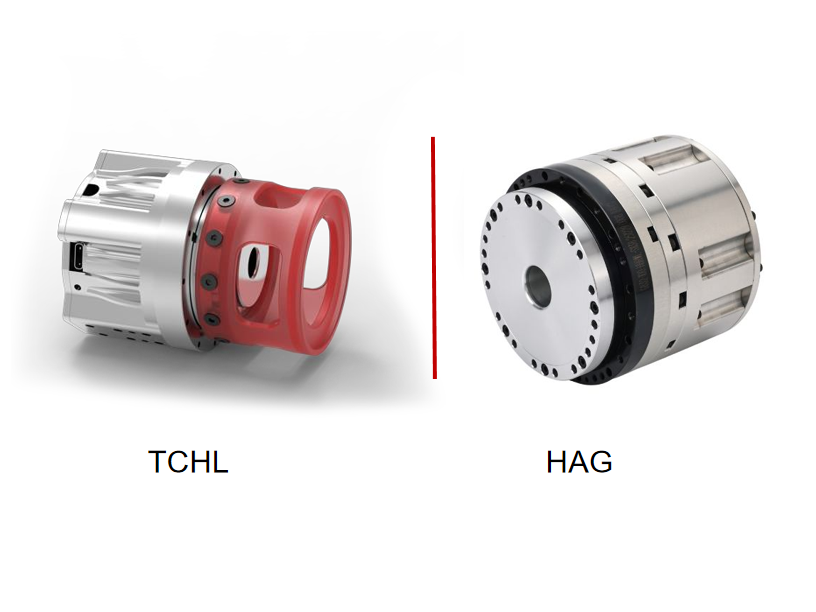
 Harmonic Drive Backlash in Arcmin: What the Specification Really Tells YouChoosing the right force control harmonic joint actuator involves more than comparing torque and dimensions. Torque sensor specifications, encoder feedback, communication protocols, functional safety, and hollow-shaft size can all affect system integration and control performance. In this guide, HONPINE Technical Director compares the TCHL and HAG harmonic joint actuator series, explaining their key differences and providing a practical selection framework for humanoid robots, collaborative manipulators, precision assembly, polishing, and other force-controlled applications.
 How to Choose a Force Control Harmonic Joint Actuator? An In-Depth Comparison of HONPINE TCHL and HAGChoosing the right force control harmonic joint actuator involves more than comparing torque and dimensions. Torque sensor specifications, encoder feedback, communication protocols, functional safety, and hollow-shaft size can all affect system integration and control performance. In this guide, HONPINE Technical Director compares the TCHL and HAG harmonic joint actuator series, explaining their key differences and providing a practical selection framework for humanoid robots, collaborative manipulators, precision assembly, polishing, and other force-controlled applications.
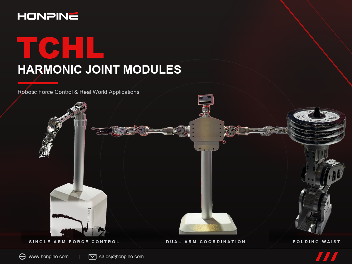
 HONPINE TCHL Harmonic Joint Modules: Robotic Force Control and Real-World ApplicationsHello everyone, I’m Theodore Li, Technical Director at HONPINE.
HONPINE TCHL harmonic joint modules have been deployed in a range of robotic motion-control applications, including dual-arm humanoid robots, single-arm compliant force control, and folding waist mechanisms for wheeled humanoid robots. As integrated motion components, they support a wide range of applications in robotics, intelligent manufacturing, and industrial automation.
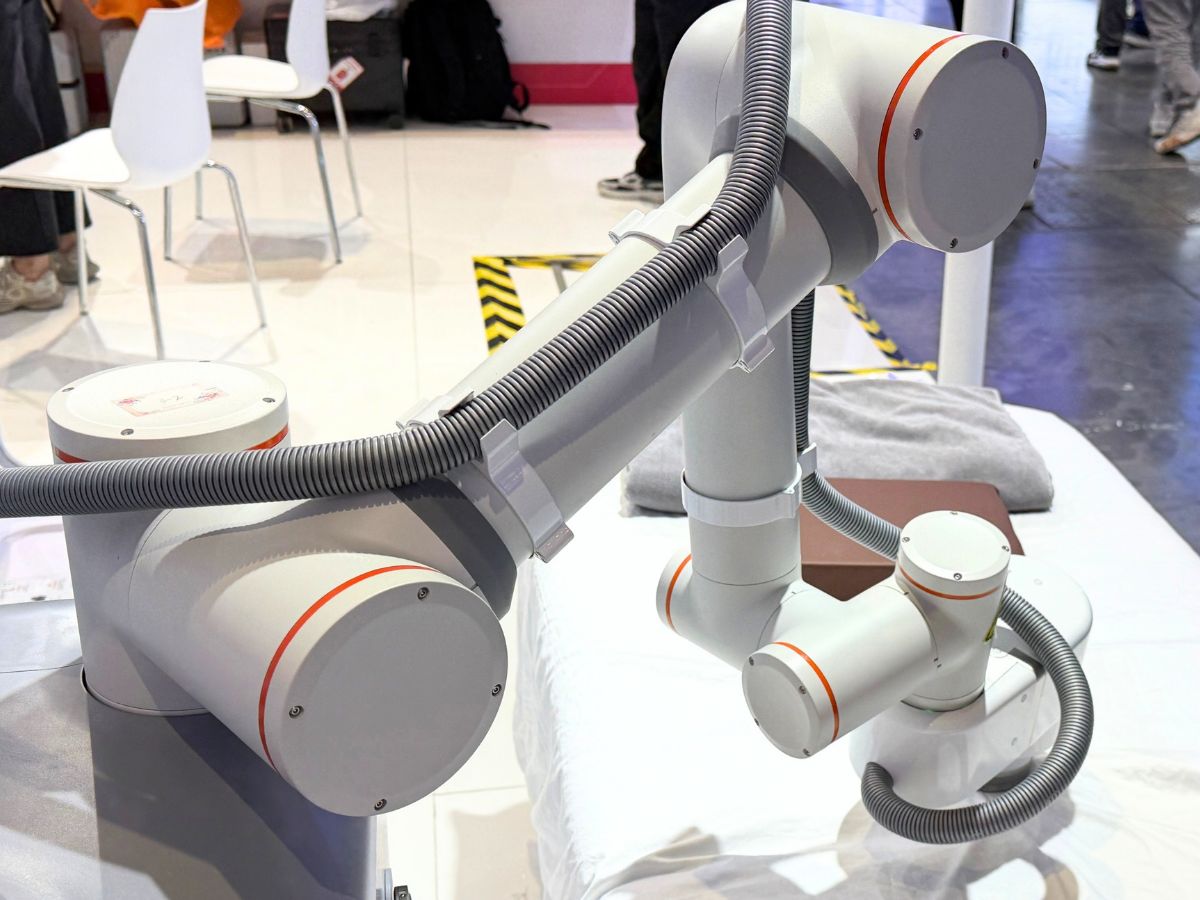
From core components to integrated motion units, HONPINE showcases the possibilities of precision transmission technology across different robotic applications through a diverse product portfolio and practical motion demonstrations. Why Bedside Physical Therapy Robots Need Force-Controlled Joint Modules?A therapy robot does not sell a robot arm; it sells a force applied to a human body. Pressure, rhythm and depth are the prescription, and position control cannot deliver them: soft tissue is compliant and time-varying, so one position command yields contact forces that differ several-fold between muscle and bone. Force-controlled harmonic joint modules turn contact force into a closed-loop variable - the only way to make dose repeatable, human contact safe and a therapist's technique teachable. Starting from one site photo of a bedside therapy robot, this article reads the configuration, sets out five reasons force control is unavoidable, settles HONPINE's TCHL-versus-HAG choice criterion by criterion, and gives the torque sensor resolution budget that picks the frame sizes.
Double Click
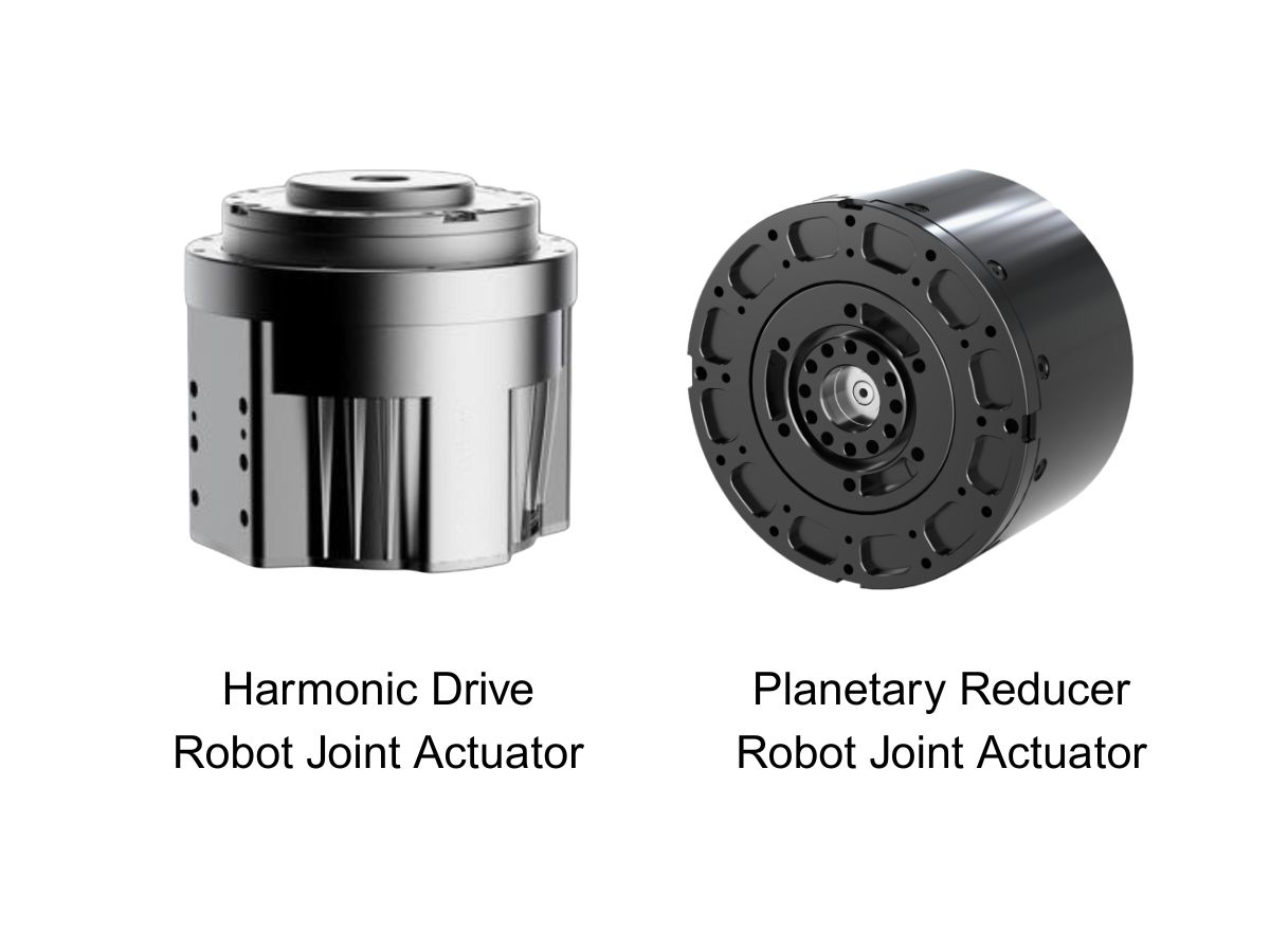
We provide harmonic drive reducer,planetary reducer,robot joint motor,robot rotary actuators,RV gear reducer,robot end effector,dexterous robot hand
 What is robot joint actuator?How to Choose the Best Robot Rotary Joint Actuator?In core robot joint transmission solutions, planetary and harmonic rotary actuators each have their own strengths. Choosing the right type based on application requirements is essential to achieve the optimal balance between performance and cost.
 DD Motors VS Harmonic Rotary ActuatorsThis article provides an in-depth comparison between Direct Drive (DD) motors and harmonic rotary actuators, covering their transmission principles, advantages and disadvantages, and typical application fields.
 OMG Ultra Compact Harmonic Drive Joint Module with Built-in Torque SensorHONPINE TCHL series harmonic drive joint module is a game-changing product that achieves disruptive improvements in multiple aspects such as lightweight design, integration level, and connection convenience. This article will analyze its revolutionary enhancements with you.
 Harmonic Drive Actuator Accuracy: Why It Should Be Evaluated at Four LevelsHarmonic drive actuator accuracy involves more than encoder resolution. Why should engineers evaluate it at four levels? Resolution, repeatability, unidirectional positioning accuracy, and bidirectional positioning accuracy describe different aspects of motion performance. Understanding these differences helps engineers select harmonic rotary actuators for semiconductor equipment, EFEM systems, and 3C automation without confusing theoretical encoder increments with actual positioning performance.
 Why Do Many Customers Choose HONPINE HPJM Harmonic Joint Modules for Just 2 mm More Hollow Bore Diameter?Why do many customers choose HONPINE HPJM harmonic joint modules for just 2 mm more hollow bore diameter? In compact robotic joints, this small dimensional difference can create a surprisingly large increase in available space. Because the cross-sectional area of a circular bore increases with the square of its diameter, an extra 2 mm can significantly improve internal cable routing and simplify system integration. This article examines the impact of hollow bore diameter, compares selected HONPINE HPJM models with comparable harmonic joint modules, and explains why bore size matters in humanoid robots, collaborative robots, and industrial automation.
 Harmonic Drive Backlash in Arcmin: What the Specification Really Tells YouChoosing the right force control harmonic joint actuator involves more than comparing torque and dimensions. Torque sensor specifications, encoder feedback, communication protocols, functional safety, and hollow-shaft size can all affect system integration and control performance. In this guide, HONPINE Technical Director compares the TCHL and HAG harmonic joint actuator series, explaining their key differences and providing a practical selection framework for humanoid robots, collaborative manipulators, precision assembly, polishing, and other force-controlled applications.
 How to Choose a Force Control Harmonic Joint Actuator? An In-Depth Comparison of HONPINE TCHL and HAGChoosing the right force control harmonic joint actuator involves more than comparing torque and dimensions. Torque sensor specifications, encoder feedback, communication protocols, functional safety, and hollow-shaft size can all affect system integration and control performance. In this guide, HONPINE Technical Director compares the TCHL and HAG harmonic joint actuator series, explaining their key differences and providing a practical selection framework for humanoid robots, collaborative manipulators, precision assembly, polishing, and other force-controlled applications.
 HONPINE TCHL Harmonic Joint Modules: Robotic Force Control and Real-World ApplicationsHello everyone, I’m Theodore Li, Technical Director at HONPINE.
HONPINE TCHL harmonic joint modules have been deployed in a range of robotic motion-control applications, including dual-arm humanoid robots, single-arm compliant force control, and folding waist mechanisms for wheeled humanoid robots. As integrated motion components, they support a wide range of applications in robotics, intelligent manufacturing, and industrial automation.
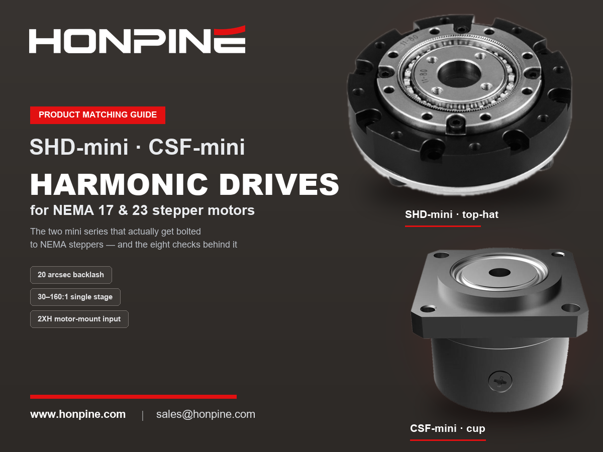
From core components to integrated motion units, HONPINE showcases the possibilities of precision transmission technology across different robotic applications through a diverse product portfolio and practical motion demonstrations. NEMA 17 & NEMA 23 Harmonic Drive Matching Guide: Pairing Stepper Motors with Harmonic ReducersPairing a stepper motor with a harmonic drive is not a budget compromise. A stepper's weak points — the coarse step angle, torque collapse above roughly 400 rpm, and the lack of a precision transmission — are exactly what a harmonic drive fixes: it pulls the operating point into the low-speed, high-torque sweet spot, refines a 1.8° step angle into arc-second resolution, and delivers near-zero backlash. This guide explains what NEMA frame sizes mean at the mounting interface, which harmonic frames match NEMA 17 and NEMA 23, the eight checks to run in order — including the input-side no-load starting torque most often missed — and the pairing's real weakness: silent failure. Includes HONPINE SHD and CSF specifications.
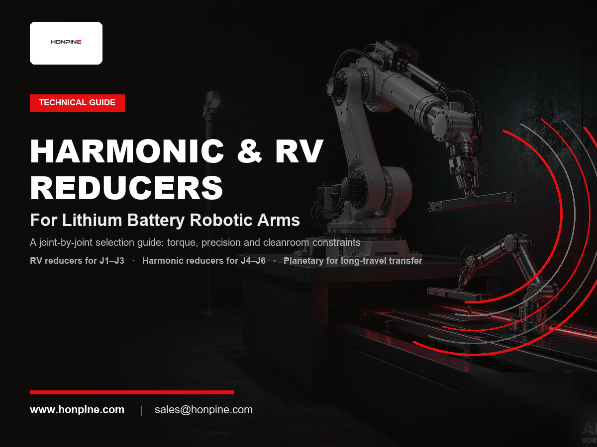
 Harmonic vs. RV Reducers for Lithium Battery Robotic Arms: A Joint-by-Joint Selection GuideIn lithium battery plants, reducer selection for a robotic arm is not about finding one "best" gearbox — it is about dividing work by joint. RV reducers take the shoulder and elbow (J1–J3), where stiffness, shock resistance, and long life matter most; harmonic reducers take the wrist (J4–J6), where near-zero backlash, high torque density, and low weight decide positioning accuracy. Planetary gearboxes cover long-travel Cartesian transfer at lower cost. Lithium battery production then adds three stricter filters: extreme repeatability (±0.02–0.05 mm), 24/7 high-duty cycles, and zero tolerance for metal particle contamination. This guide explains the logic behind joint-by-joint selection, compares the three reducer types, and maps typical configurations for every station.
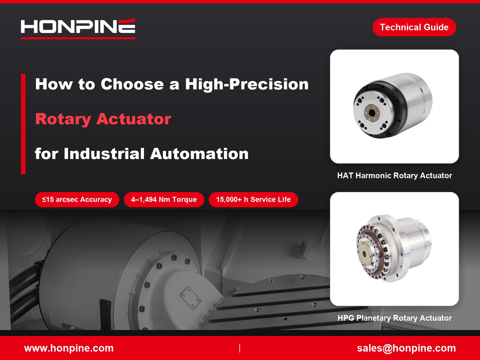
 How to Choose High-Precision Rotary Actuators for Industrial Automation?High-precision rotary actuators play an important role in industrial automation, where positioning accuracy, repeatability, durability and installation flexibility directly affect equipment performance. HONPINE offers four main series of precision rotary actuators, including HAT, HAM and HAS harmonic rotary actuators and HPG low-backlash planetary actuators. With torque ratings ranging from 4 to 1,494 Nm across the product range, these solutions are designed for applications in semiconductor manufacturing, 3C automation, laser processing and CNC machine tools. Learn how to identify the right rotary actuator based on operating conditions, precision requirements and mechanical integration needs.
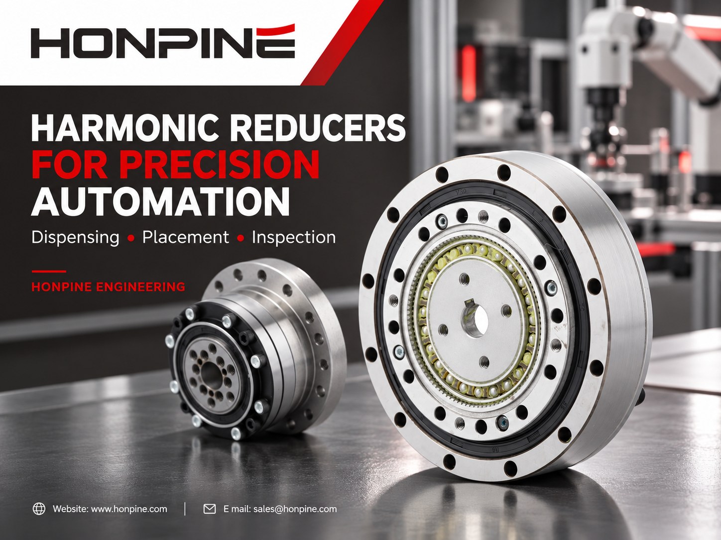
 Why Are Harmonic Reducers Suitable for High-Precision Automation Equipment?Precision automation equipment depends on consistent rotary motion, reliable positioning and compact transmission design. From dispensing head orientation and component angular alignment to automated inspection indexing, harmonic reducers offer a practical solution for applications requiring low backlash and high reduction ratios in limited installation space. This article explains how harmonic reducers support repeatable motion, compares key design configurations, and outlines how to select a suitable reduction ratio and reducer structure based on load, speed, accuracy and machine cycle-time requirements.