The A-Z of Harmonic Reducers: Your Go-To Resource for Precision Mechanics
1.What is a harmonic reducer?
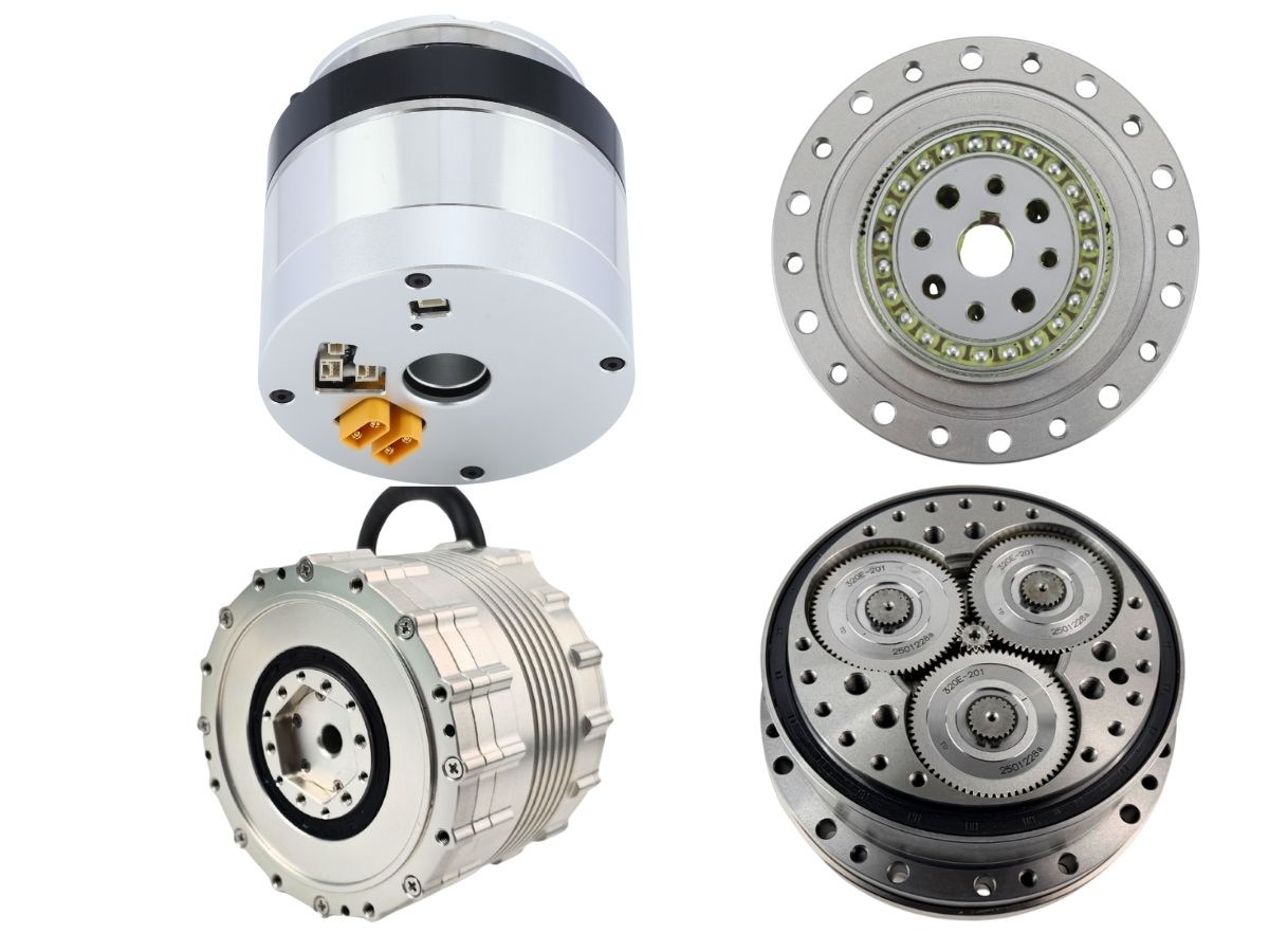
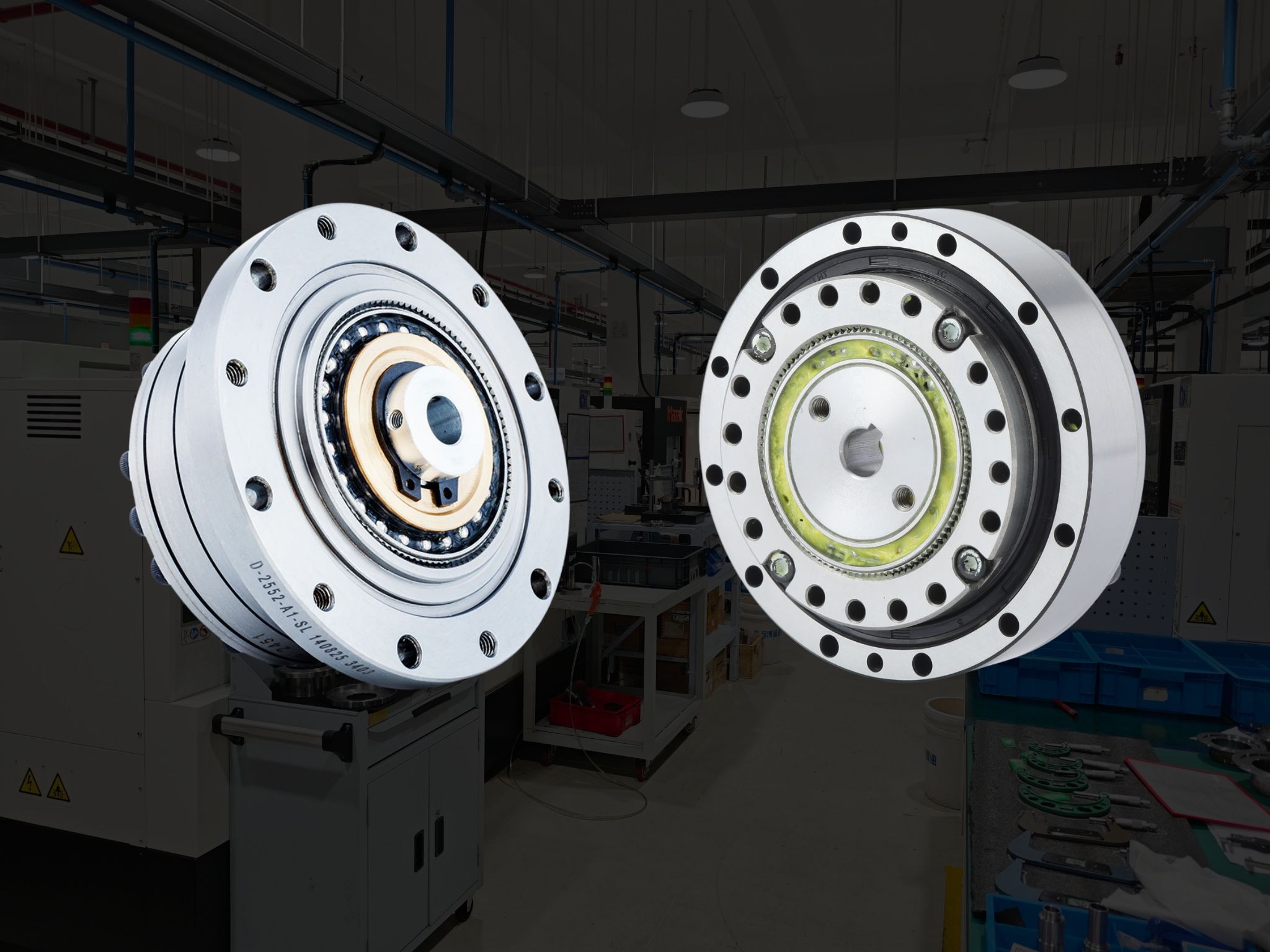
The harmonic reducer was invented by C.W. Musser of the United States. It is a unique mechanical gear system characterized by zero backlash, high precision, high torque, and a high reduction ratio in a compact and lightweight structure.
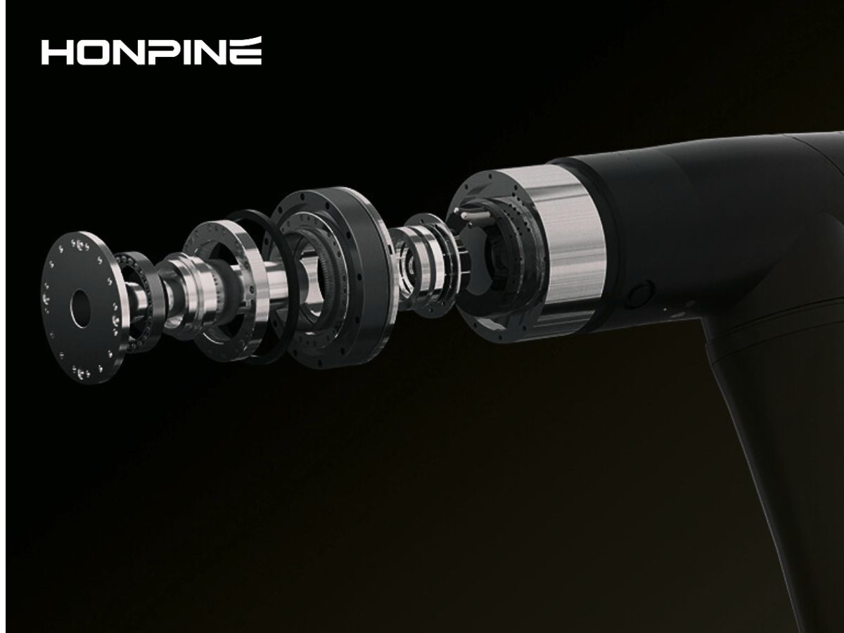
2.The structure of the harmonic reducer
Key components:
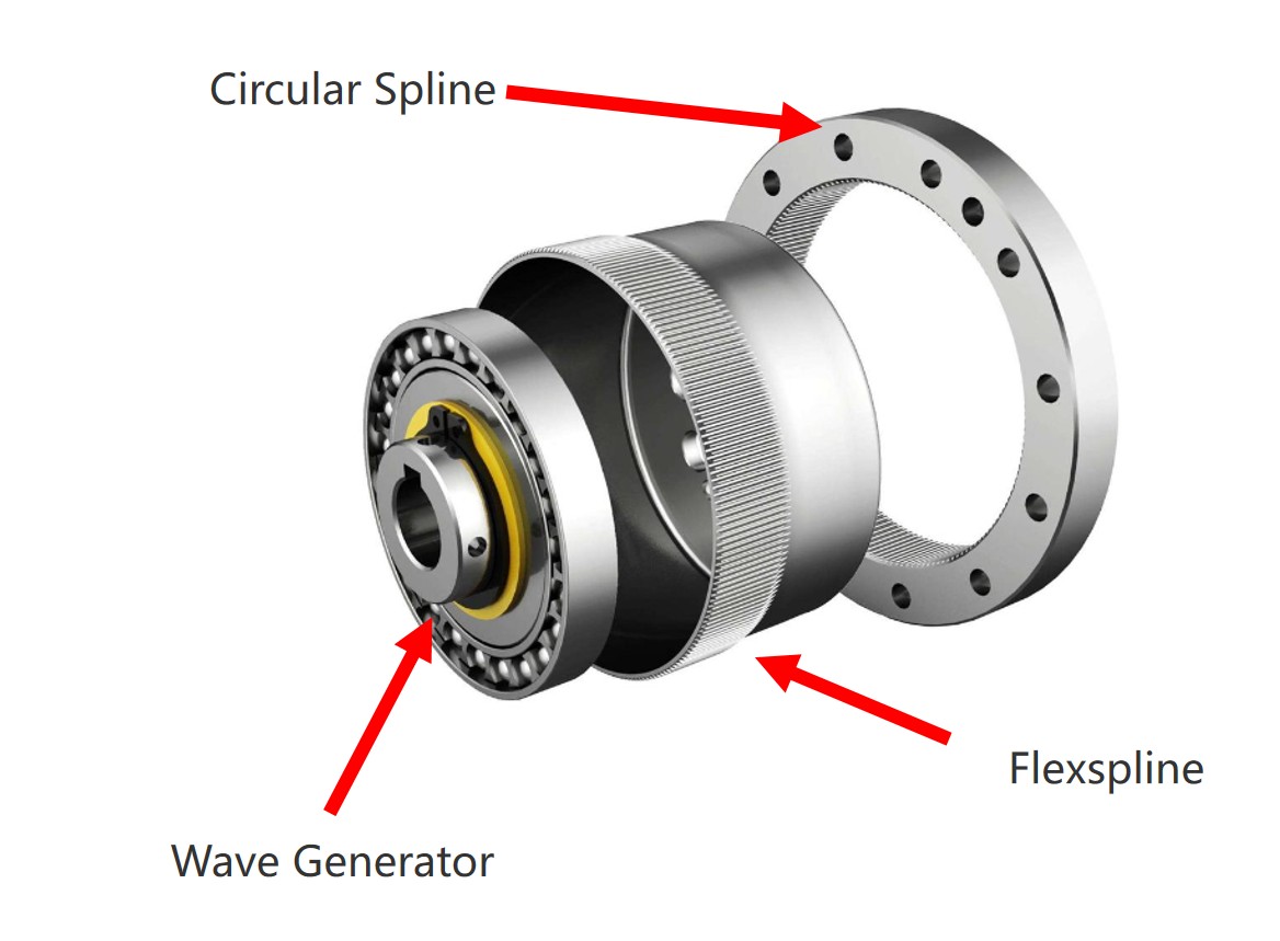
Circular Spline: A rigid gear with an internal gear ring.
Flexspline: A flexible gear with an external gear ring.
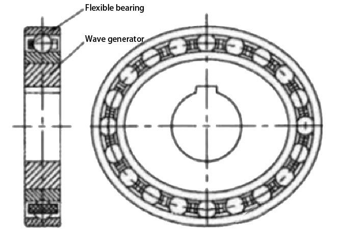
Wave Generator: An elliptical cam with a thin-walled ball bearing on its outer periphery. The bearing’s inner ring is fixed to the cam, while the outer ring deforms elastically via the balls.
3.Origin of the Name "Harmonic Reducer"
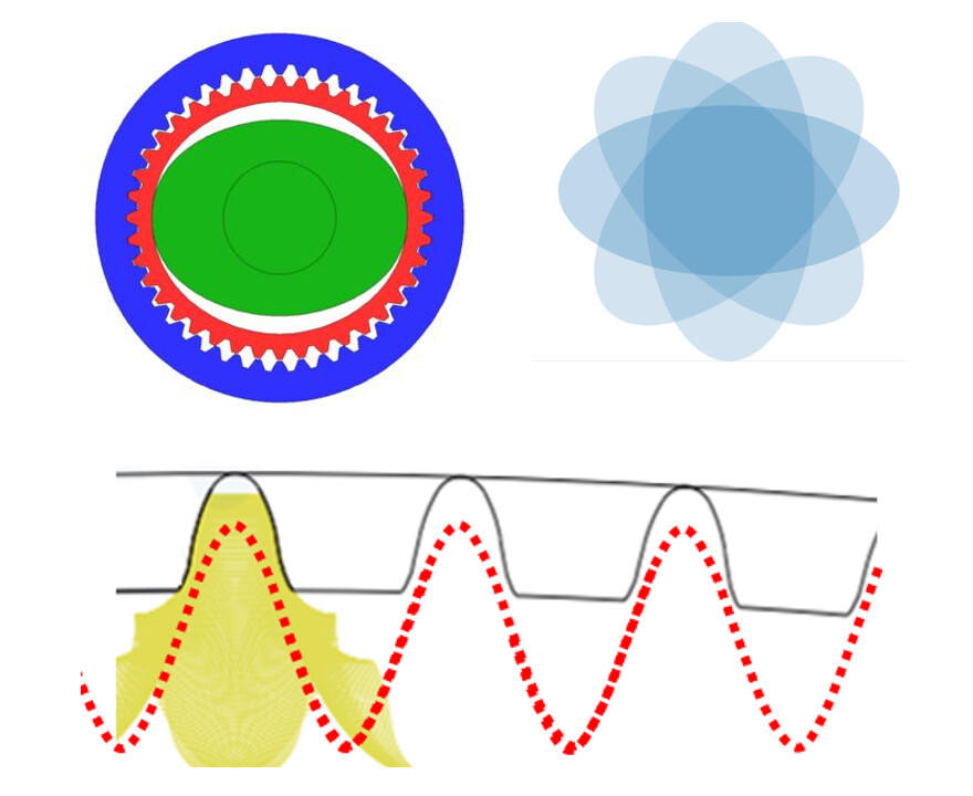
The wave generator has an elliptical structure. When rotated, it forces the flexspline to deform continuously. During this process, the gear teeth alternate between meshing in, meshing out, and disengaging, creating a "staggered tooth" motion.
The resulting movement follows a wave-like path, and the radial displacement of any point on the gear ring resembles a sine wave—hence the term "harmonic."
4.Common Flexspline Shapes
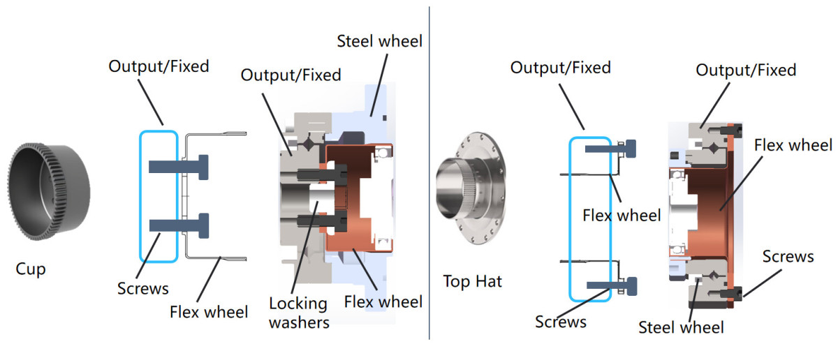
Cup-shaped flexspline
Top-hat-shaped flexspline
5.Common Housing Shapes
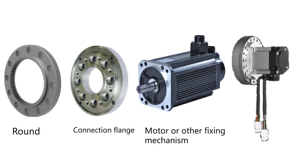
Round housing
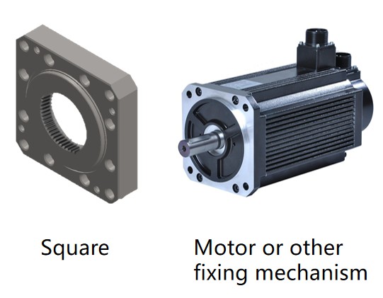
Square housing
6.What is a Wave Generator in a Harmonic Reducer?
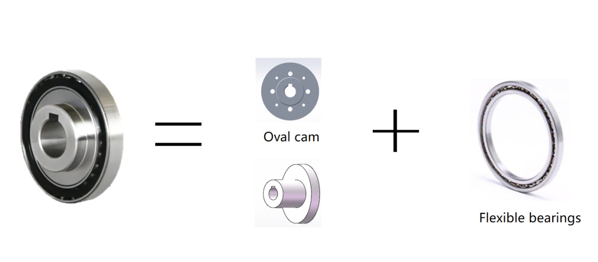
The wave generator consists of a flexible bearing and an elliptical cam. It is typically installed at the reducer’s input end. The bearing’s inner ring is fixed to the cam, while the outer ring deforms into an ellipse via the balls.
7.Common Wave Generator Designs
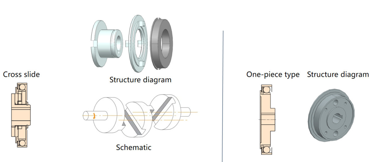
Wave generators are classified into two types based on cam design:
Oldham coupling (cross-slider) type
Integrated type
8.Relationship Between the Wave Generator and Flexspline
Flexible bearings differ from standard bearings—their outer rings are thin and prone to radial deformation. Before cam installation, the ring is circular; after installation, it becomes elliptical.
During operation:
The inner ring (mounted on the rigid cam) endures cyclic stress.
The outer ring (mounted on the flexspline) deforms with the flexspline, enduring both cyclic and alternating stress loads.
9.Harmonic Reducer Bearing Accuracy Grades
Precision grades (ascending order): P0, P6, P5, P4, P2
Grade 0: For systems with rotational precision >10 μm (e.g., general machinery, automotive transmissions).
Grades 6/5: For systems with precision of 5–10 μm or higher speeds (e.g., lathe spindle supports).
Grades 4/2: For ultra-precision systems (<5 μm) or very high speeds (e.g., precision grinders, coordinate measuring machines).
10. Harmonic Reducer Installation Precautions
A. Install in a clean environment to prevent foreign debris from damaging the reducer.
B. Ensure the gear teeth and flexible bearing are fully lubricated. Avoid mounting with the gear teeth facing upward, as this reduces lubrication effectiveness.
C. After installing the cam, verify that the flexspline and circular spline mesh symmetrically at 180°. Misalignment causes vibration and premature wear.
D. After installation, run at low speed (100 RPM) initially. Stop immediately if abnormal vibration or noise occurs to avoid damage.
Read More
Learn more about the story of HONPINE and industry trends related to precision transmission.
Double Click
We provide harmonic drive reducer,planetary reducer,robot joint motor,robot rotary actuators,RV gear reducer,robot end effector,dexterous robot hand
