








AGV Drive System Selection: How to Choose Between Differential Drive, Steer Drive, and Mecanum Hub Motors?
The correct sequence for AGV drive system selection is to determine the drive mechanism first — differential drive, steer drive, or Mecanum wheel drive — and then select the wheels. The mechanism determines the number of wheels, load directions, axle-load distribution, and potential failure modes. Comparing wheel specifications before defining the drive mechanism means making a wheel selection before the actual load conditions have been established.
The requirements for wheels can be summarized into four common parameters: wheel diameter consistency, tread friction and wear characteristics, wheel-core concentricity and interface accuracy, and bearing and load-carrying configuration. However, the priority of these parameters varies significantly between different drive mechanisms.
Why Should the Drive Mechanism Be Determined Before Selecting the Hub Motor?
In many AGV projects, wheels are often discussed relatively late. The navigation system, scheduling logic, and vehicle structure are defined first, while the wheels are treated as the final execution component to be purchased.
There is nothing fundamentally wrong with this sequence. The problem occurs when wheels are treated as standardized purchasing components — for example, selecting a diameter based only on load capacity, choosing a tread hardness based on experience, and installing the wheels without further system-level analysis.
After the AGV starts operating, problems such as directional deviation, positioning errors, and uneven tread wear may appear. Troubleshooting is often directed toward navigation or control algorithms, while the actual root cause may lie in the mismatch between the drive mechanism and the wheel.
1. Transmission Chain One: The Drive Mechanism Determines the Direction of Wheel Loading
The same polyurethane-coated wheel can experience completely different forces depending on the drive mechanism.
In a differential-drive system, a passive wheel experiences lateral forces as it follows the vehicle body. During turning, the tread can experience lateral scrubbing against the floor.
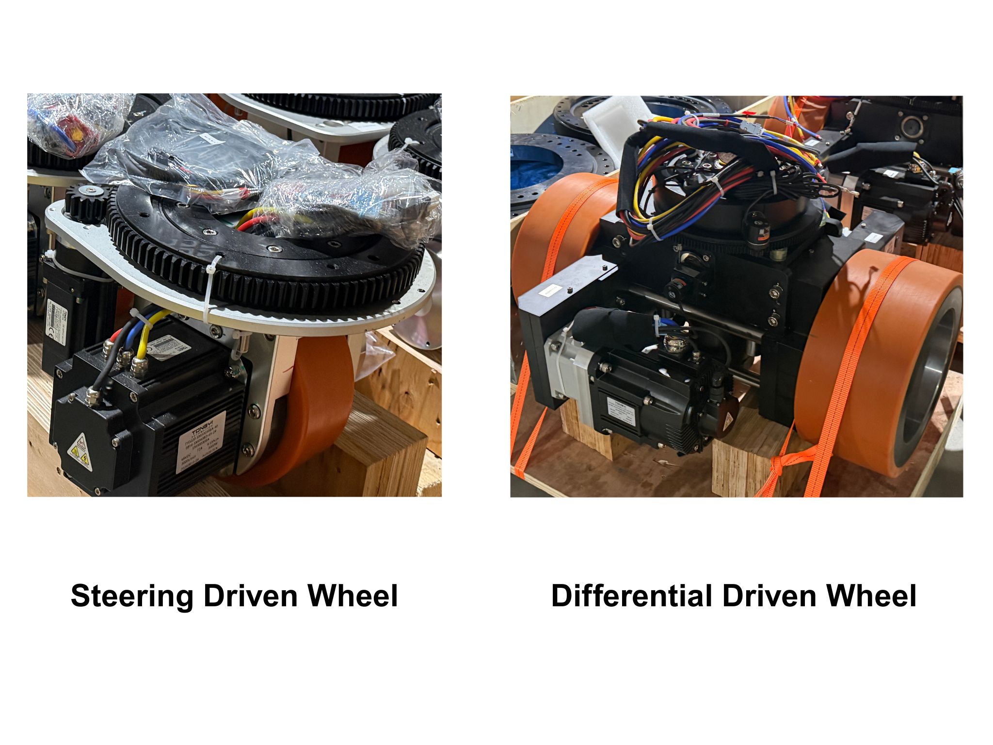
In a steer-drive system, the drive wheel must withstand not only traction and vertical loads, but also the steering reaction torque transmitted through the steering mechanism and lateral scrubbing during steering.
For a Mecanum wheel, the rollers simultaneously experience radial pressure and axial force components. The loading condition is therefore more complex.
Because the direction of force changes, the required tread formulation also changes.
Applications where traction is the primary requirement generally need a stable coefficient of friction and good wear resistance. A harder, wear-resistant tread formulation is often more suitable for these conditions.
For applications where the wheel is mainly being dragged or subjected to lateral scrubbing, the tread needs to minimize floor marking and heat generation. A softer formulation with lower rolling resistance may therefore be more appropriate.
HanKe's Eamflex 93A tread system is designed toward high wear resistance, while the Saxflex 75A tread system is designed with greater emphasis on floor protection. These two tread directions correspond to the different loading conditions described above. Choosing the wrong tread characteristics may not reveal a problem immediately and can instead become apparent only after several hundred hours of operation.
2. Transmission Chain Two: The Drive Mechanism Determines Axle-Load Distribution and Load Transfer
Using an equal static load distribution to estimate the load on each wheel is a common simplification during the selection stage.
For example, assume a four-wheel AGV with a total loaded mass of 4,000 kg. A simple static calculation would give 1,000 kg per wheel.
However, during acceleration, braking, and turning, the load transfers between wheels. The approximate load-transfer amount can be estimated using:
ΔF = m × a × h ÷ B
where m is the total vehicle mass in kilograms, a is the longitudinal or lateral acceleration in meters per second squared, h is the center-of-gravity height in meters, and B is the track width in meters.
Using a representative set of parameters:
m = 4,000 kg
a = 0.5 m/s²
h = 0.5 m
B = 0.8 m
The calculated load transfer is:
ΔF = 4,000 × 0.5 × 0.5 ÷ 0.8 = 1,250 N
This corresponds to approximately 127 kgf of additional vertical load transferred from the inner wheel to the outer wheel.
The significance of this calculation is that the actual load on an individual wheel under dynamic conditions can be higher than the static equal-distribution value. If the original selection has very little load margin, turning, climbing, or emergency braking can become the conditions under which problems are first exposed.
The exact load increase on each wheel depends on the wheel configuration and suspension arrangement and should be calculated using the actual vehicle parameters. However, the general principle is clear: the more frequently the AGV performs omnidirectional movement and steering, the more important dynamic load transfer becomes during wheel selection.
A single-steer-wheel configuration is a typical example. When one drive point handles both propulsion and steering, the load requirement of that wheel can be much higher than the value obtained by simply dividing the total vehicle weight by the number of wheels.
The flange interface also requires greater accuracy because angular deviation or runout in the steering unit can be directly transferred into vehicle attitude errors.
3. Transmission Chain Three: The Drive Mechanism Determines Where the Main Wheel-Related Bottleneck Occurs
The main wear and precision limitations are not located in the same place for all three drive mechanisms.
For differential drive, the key issue is the diameter consistency of the left and right drive wheels. The differential controller assumes that the wheel diameters are approximately equal. If an actual diameter difference exists, the same rotational-speed command will produce different linear velocities on the two sides, causing the vehicle heading to deviate.
For steer drive, the main issues are flange-interface concentricity and steering-induced tread wear. Runout or misalignment at the steering-unit mounting surface can be amplified into vehicle attitude variation, while repeated lateral scrubbing can create an uneven wear band on the tread.
For Mecanum wheels, the main bottleneck is the roller assembly itself. The rollers are independent components covered with rubber or polyurethane. They carry both the load and sliding friction, so their wear rate can be higher than that of conventional wheel treads. Uneven wear among the rollers on four wheels can appear as directional and displacement errors during omnidirectional movement.
When these three transmission chains are considered together, it becomes clear why the selection sequence should not be reversed.
The drive mechanism must first be defined so that the direction of wheel loading, number of wheels, and dynamic loads can be established. Only then can engineers determine which wheel parameters require additional design margin.
Selecting a wheel first means optimizing a component before its actual loading environment has been fully defined.
Multidimensional Comparison of Three AGV Drive Mechanisms
Kinematic and Structural Comparison
Wheel Requirement Comparison
Operating Conditions and Floor Compatibility
Failure Modes and Maintenance Priorities
A Seven-Step AGV Hub Motor Selection Process
The following seven-step process brings the logic discussed above into an actionable sequence.
These seven steps can be discussed at different stages of a project, but the sequence should generally not be reversed. The output from each step becomes the input for the next.
Step 1: Define the Required Degrees of Freedom
Start by answering three questions:
Does the AGV need lateral translation?
Does it need to rotate in place?
Is there a strict limit on the turning radius?
If both lateral translation and in-place rotation are unnecessary, differential drive is often sufficient.
If either capability is required, steer drive and Mecanum drive should be included in the comparison.
Step 2: Define Floor Conditions and Path Characteristics
Record the floor type, flatness, joints and slopes, cleanliness requirements, oil and water exposure, as well as the typical travel distance and turning frequency for each mission.
This information affects both the feasibility of the drive mechanism and the required tread formulation.
Step 3: Calculate Axle Loads Including Dynamic Load Transfer
Use:
ΔF = m × a × h ÷ B
to estimate the load transfer during dynamic operation.
Add the calculated dynamic increment to the static load distribution to obtain the wheel load requirement for selection, and specify the operating speed at the same time.
Load capacity should always be stated together with the operating speed.
For example, specifying the allowable load at 4 km/h is meaningful, while a load rating without a corresponding speed condition does not provide a complete basis for comparison.
Step 4: Determine Wheel Diameter and Width
Wheel diameter affects obstacle-crossing capability, rolling resistance, and load capacity.
Wheel width affects ground pressure and lateral stability.
In heavy-load applications, appropriately increasing wheel diameter or width can be more effective for reducing contact pressure than simply increasing tread hardness.
Step 5: Determine Tread Hardness and Formulation Direction
For wheel positions where traction is the priority, a relatively harder and more wear-resistant tread formulation is generally appropriate.
For passive wheels where low rolling resistance and floor protection are more important, a softer and lower-resistance formulation may be preferred.
For wheel positions exposed to frequent steering scrubbing, the tread formulation should balance wear resistance and resistance to lateral abrasion.
HanKe typically provides formulation recommendations according to individual wheel positions rather than applying one identical tread formulation to the entire AGV.
Step 6: Determine Wheel-Core Structure and Bearing Configuration
Wheel-core material, surface treatment, flange or keyway interface, bearing type, and bearing-clearance class should be matched with the drive mechanism, reducer, and overall vehicle load spectrum.
Bearing selection should be considered together with the wheel-core structure. Selecting the two independently can lead to rework during assembly.
Step 7: Define Pairing Rules and Acceptance Criteria
Specify the allowable diameter difference between coaxial left and right wheels, the consistency requirements among multiple wheels on the same vehicle, and the data that must be checked during acceptance testing.
This final step converts the conclusions from the previous six steps into measurable and verifiable technical requirements.
Conclusion
AGV wheel selection should not begin with wheel diameter, tread hardness, or rated load in isolation.
The correct approach is to first define the drive mechanism, then determine the resulting load direction, wheel configuration, dynamic load distribution, and precision requirements. Only after these conditions are established can the appropriate hub motor, wheel diameter, tread formulation, wheel-core structure, bearing configuration, and matching requirements be selected.
Differential drive, steer drive, and Mecanum wheel drive each have different kinematic characteristics, load paths, precision bottlenecks, and maintenance requirements. A wheel that performs well in one configuration may not be the appropriate choice for another.
For AGV and AMR projects, the wheel and drive mechanism should therefore be treated as one integrated motion system rather than as two independent components.
Contact HONPINE to discuss your AGV application requirements and find a suitable AGV hub motor solution.
Read More
Learn more about the story of HONPINE and industry trends related to precision transmission.
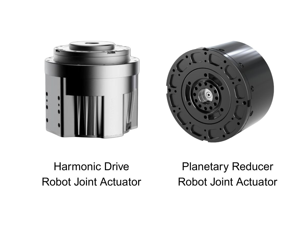
 What is robot joint actuator?How to Choose the Best Robot Rotary Joint Actuator?In core robot joint transmission solutions, planetary and harmonic rotary actuators each have their own strengths. Choosing the right type based on application requirements is essential to achieve the optimal balance between performance and cost.
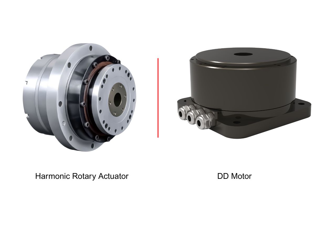
 DD Motors VS Harmonic Rotary ActuatorsThis article provides an in-depth comparison between Direct Drive (DD) motors and harmonic rotary actuators, covering their transmission principles, advantages and disadvantages, and typical application fields.
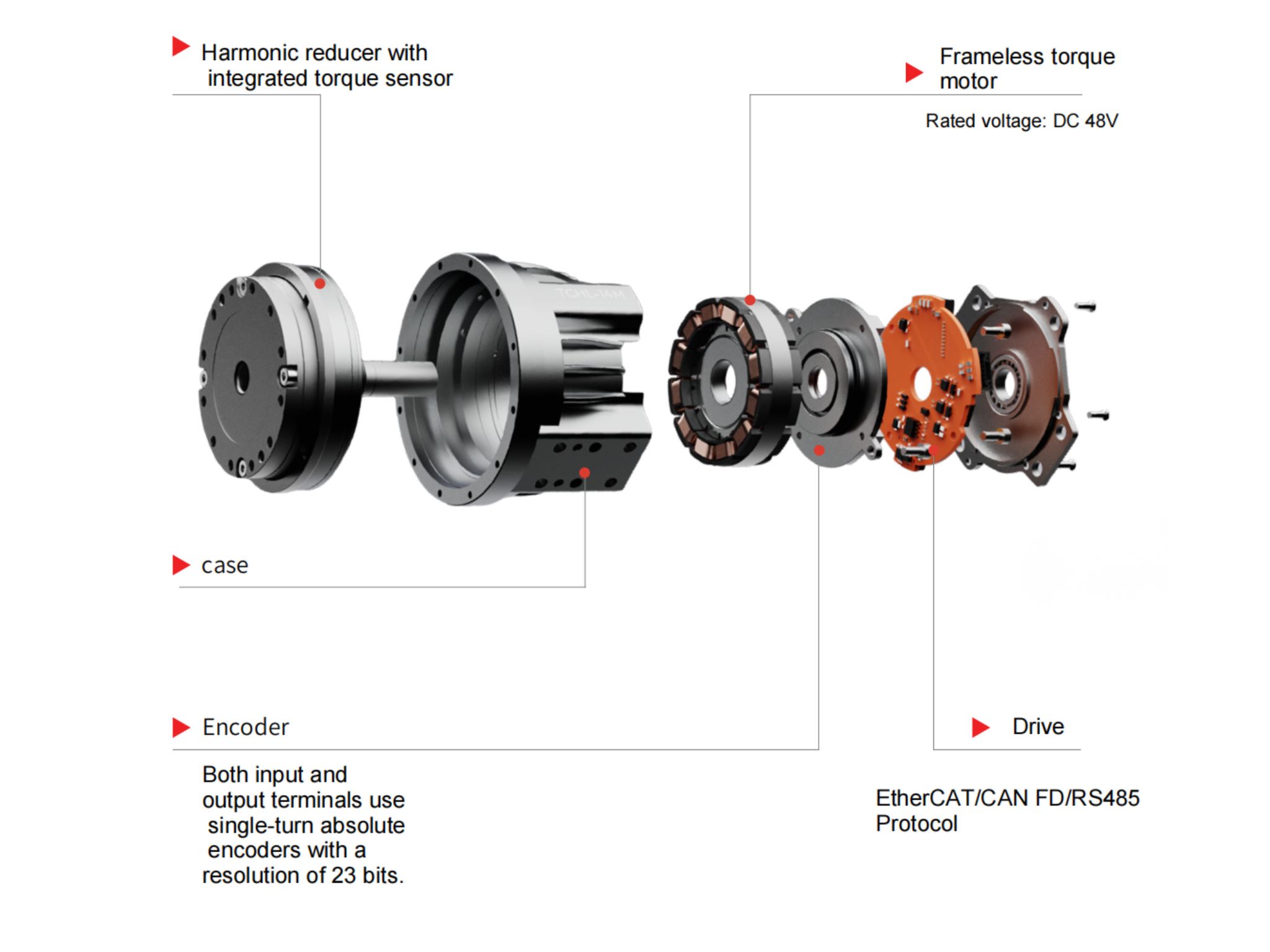
 OMG Ultra Compact Harmonic Drive Joint Module with Built-in Torque SensorHONPINE TCHL series harmonic drive joint module is a game-changing product that achieves disruptive improvements in multiple aspects such as lightweight design, integration level, and connection convenience. This article will analyze its revolutionary enhancements with you.
 The Role of Harmonic Drive Gears in Achieving 5–10 μm Accuracy in Dental Milling MachinesA dental milling machine is a CNC machining system used to directly process digital dental models into restorations such as crowns, bridges, veneers, inlays, and implant abutments. Dental milling machines require far higher operational accuracy and motion stability than ordinary equipment. This article explains how harmonic drive gear help dental milling machines achieve stable, continuous, and controllable operation.
 Why Are Harmonic Rotary Actuators Perfect for Medical Equipment?Harmonic rotary actuators (typically integrated systems consisting of a harmonic drive reducer, frameless torque motor, encoder, and optional brake) are regarded as key components in medical equipment. The core reason is that they simultaneously meet the most stringent medical requirements for precision, compact size, safety, and controllability. The following explanation is structured from three perspectives: technical characteristics, application scenarios, and medical value.
 High-Precision RV Reducers Perfectly Matched for Walking RobotsThe walking axis of a robot is a core component for power transmission and support. RV reducers provide extremely high rigidity, precision, and torque while maintaining a compact size and exceptional reliability, making them an ideal match for the demanding requirements of walking robot joints in terms of load capacity, impact resistance, and precision.
 Why Does an RV Reducer Need Profile Modification? How to Further Reduce Backlash and Transmission Error?An RV Reducer is designed to deliver high torque, high stiffness, and precise motion for demanding applications such as robotic joints, industrial rotary tables, and precision machinery. However, achieving low backlash and stable transmission accuracy requires more than high-precision machining. Cycloidal profile modification must also account for manufacturing tolerances, assembly errors, load-induced deformation, thermal expansion, and lubrication conditions. In this article, we examine why RV reducers require profile modification, how different modification methods affect meshing, and how engineers can further control backlash and transmission error through profile design, error budgeting, structural analysis, precision manufacturing, and validation testing.
 Hollow Robot Joint Module: Why Cable Routing Matters in Robotic Joints?A hollow robot joint module provides an internal passage for power cables, signal lines, pneumatic tubes, and other end-effector connections. Compared with external cable routing, a hollow joint module can help reduce cable exposure, improve system integration, and create a cleaner motion path for robotic arms. This article explains why internal cable routing matters in robotic joints and what to consider when selecting a hollow joint module for robotic applications.
 Large-Bore Harmonic Joint Actuator for Humanoid Robot Waist Joints: A Practical Selection GuideThe humanoid robot waist joint is one of the most demanding motion joints in a humanoid robot. Unlike conventional robotic arm joints, it supports the upper body while handling bending, twisting, posture transitions, and continuously changing dynamic loads. At the same time, the limited internal space must accommodate power cables, signal lines, sensors, and structural components. These requirements make a large-bore harmonic joint actuator an important option for humanoid robot waist joints. This article explains how to select a suitable harmonic joint actuator by considering hollow bore size, dynamic torque, reduction ratio, mechanical rigidity, integration, and service life.
 Nabtesco RV vs Harmonic Drive vs WITTENSTEIN: Why Backlash-Free Planetary Actuators Are EmergingNabtesco RV, Harmonic Drive, and WITTENSTEIN have each established proven transmission solutions for robotics, machine tools, automation, and precision motion control. However, applications requiring both arc-second-level positioning and high mechanical rigidity can expose different trade-offs between backlash, torsional stiffness, load capacity, and transmission accuracy. This has created growing interest in a backlash-free planetary actuator that combines the rigidity and torque density of planetary transmission with advanced backlash compensation. In this article, we compare the characteristics of Nabtesco RV, Harmonic Drive, and WITTENSTEIN precision planetary gearboxes, and examine where a backlash-free planetary actuator can provide an alternative solution.
 Robot Joint Actuator Selection: From Inertia Matching to System-Level OptimizationSelecting a robot joint actuator is not simply a matter of matching motor torque or achieving a suitable inertia ratio. In a real robotic system, reduction ratio, load spectrum, thermal performance, mechanical stiffness, transmission nonlinearity, encoder architecture, control bandwidth, and service life all interact to determine the final result. A joint may meet its peak torque requirement and still experience vibration, overheating, positioning errors, or premature wear in real operation. This article examines the engineering logic behind robot joint actuator selection and explains why moving from single-parameter matching to system-level optimization can lead to more reliable and predictable robotic joint performance.
 HONPINE HAG Robot Joint Module Undergoing Pre-Shipment InspectionThe HONPINE HAG Robot Joint Module is currently undergoing pre-shipment inspection before delivery.
Double Click
We provide harmonic drive reducer,planetary reducer,robot joint motor,robot rotary actuators,RV gear reducer,robot end effector,dexterous robot hand
 What is robot joint actuator?How to Choose the Best Robot Rotary Joint Actuator?In core robot joint transmission solutions, planetary and harmonic rotary actuators each have their own strengths. Choosing the right type based on application requirements is essential to achieve the optimal balance between performance and cost.
 DD Motors VS Harmonic Rotary ActuatorsThis article provides an in-depth comparison between Direct Drive (DD) motors and harmonic rotary actuators, covering their transmission principles, advantages and disadvantages, and typical application fields.
 OMG Ultra Compact Harmonic Drive Joint Module with Built-in Torque SensorHONPINE TCHL series harmonic drive joint module is a game-changing product that achieves disruptive improvements in multiple aspects such as lightweight design, integration level, and connection convenience. This article will analyze its revolutionary enhancements with you.
 Why Does an RV Reducer Need Profile Modification? How to Further Reduce Backlash and Transmission Error?An RV Reducer is designed to deliver high torque, high stiffness, and precise motion for demanding applications such as robotic joints, industrial rotary tables, and precision machinery. However, achieving low backlash and stable transmission accuracy requires more than high-precision machining. Cycloidal profile modification must also account for manufacturing tolerances, assembly errors, load-induced deformation, thermal expansion, and lubrication conditions. In this article, we examine why RV reducers require profile modification, how different modification methods affect meshing, and how engineers can further control backlash and transmission error through profile design, error budgeting, structural analysis, precision manufacturing, and validation testing.
 Hollow Robot Joint Module: Why Cable Routing Matters in Robotic Joints?A hollow robot joint module provides an internal passage for power cables, signal lines, pneumatic tubes, and other end-effector connections. Compared with external cable routing, a hollow joint module can help reduce cable exposure, improve system integration, and create a cleaner motion path for robotic arms. This article explains why internal cable routing matters in robotic joints and what to consider when selecting a hollow joint module for robotic applications.
 Large-Bore Harmonic Joint Actuator for Humanoid Robot Waist Joints: A Practical Selection GuideThe humanoid robot waist joint is one of the most demanding motion joints in a humanoid robot. Unlike conventional robotic arm joints, it supports the upper body while handling bending, twisting, posture transitions, and continuously changing dynamic loads. At the same time, the limited internal space must accommodate power cables, signal lines, sensors, and structural components. These requirements make a large-bore harmonic joint actuator an important option for humanoid robot waist joints. This article explains how to select a suitable harmonic joint actuator by considering hollow bore size, dynamic torque, reduction ratio, mechanical rigidity, integration, and service life.
 Nabtesco RV vs Harmonic Drive vs WITTENSTEIN: Why Backlash-Free Planetary Actuators Are EmergingNabtesco RV, Harmonic Drive, and WITTENSTEIN have each established proven transmission solutions for robotics, machine tools, automation, and precision motion control. However, applications requiring both arc-second-level positioning and high mechanical rigidity can expose different trade-offs between backlash, torsional stiffness, load capacity, and transmission accuracy. This has created growing interest in a backlash-free planetary actuator that combines the rigidity and torque density of planetary transmission with advanced backlash compensation. In this article, we compare the characteristics of Nabtesco RV, Harmonic Drive, and WITTENSTEIN precision planetary gearboxes, and examine where a backlash-free planetary actuator can provide an alternative solution.
 Robot Joint Actuator Selection: From Inertia Matching to System-Level OptimizationSelecting a robot joint actuator is not simply a matter of matching motor torque or achieving a suitable inertia ratio. In a real robotic system, reduction ratio, load spectrum, thermal performance, mechanical stiffness, transmission nonlinearity, encoder architecture, control bandwidth, and service life all interact to determine the final result. A joint may meet its peak torque requirement and still experience vibration, overheating, positioning errors, or premature wear in real operation. This article examines the engineering logic behind robot joint actuator selection and explains why moving from single-parameter matching to system-level optimization can lead to more reliable and predictable robotic joint performance.
 How to Choose a Small Harmonic Actuator?HONPINE Series 11 small harmonic actuators provide a compact, high-performance rotary motion solution for precision automation applications. Available with hollow or solid shafts, 48V or 220V options, optional brakes, absolute encoders, and different reduction ratios, the Series 11 is designed for applications requiring compact dimensions, controlled torque, and precise positioning.
 How to Choose a Wheel Motor for a Heavy-Duty AGV? Key Challenges from Dynamic Loads to 120-Ton AGV Drive Wheel SystemsSelecting a Heavy-Duty AGV Wheel Motor is more than matching motor power or rated torque to the vehicle's payload. As AGVs move from conventional material handling to multi-ton and even 120-ton-class applications, the drive wheel system must handle dynamic loads, acceleration, braking, turning forces, traction, and long-term mechanical stress. The actual challenge lies in matching wheel load capacity, wheel-end torque, gearbox performance, steering architecture, suspension, and chassis design under real operating conditions. This article examines the key challenges of Heavy-Duty AGV Wheel Motor selection and explains how Steering Drive Wheels and Differential Drive Wheels can be evaluated for different heavy-duty AGV applications.
 Why Is a Planetary Gearbox an Ideal Partner for Servo Motors in CNC, AGV, Solar and Lithium Battery Equipment?A servo motor can deliver high speed, precise control and fast dynamic response, but the transmission system between the motor and the machine also determines how effectively these capabilities are transferred to the load. A planetary gearbox is widely paired with servo motors because its coaxial structure, high efficiency, low backlash, high torsional rigidity and flexible reduction ratios make it suitable for a broad range of motion systems. From CNC machine tools and industrial automation to AGVs, photovoltaic equipment and lithium battery production lines, planetary gearboxes can provide a practical balance between precision, performance and cost. This article explains why planetary gearboxes work well with servo motors and how engineers can select the right transmission for different applications.
 AGV Drive System Selection: How to Choose Between Differential Drive, Steer Drive, and Mecanum Hub Motors?As AGVs become more widely used in intralogistics, manufacturing, warehousing and heavy-load material handling, selecting the right drive system is becoming increasingly important. Differential drive, steer drive and Mecanum drive each have different requirements for wheel structure, load distribution, traction, steering and motion control. These differences directly affect AGV positioning accuracy, turning performance, wheel wear and long-term reliability. In this article, we compare the three common AGV drive systems and explain how to select the appropriate AGV hub motor and wheel configuration according to the vehicle structure, operating conditions, load and required mobility.