








Robot Joint Actuator Selection: From Inertia Matching to System-Level Optimization
In robot joint actuator selection, inertia matching is an important engineering consideration, but it should not be treated as the entire selection strategy. A robot joint actuator is not simply a motor combined with a gearbox. Its actual performance is determined by the interaction of the motor, reduction mechanism, bearings, encoder, drive system, mechanical structure, thermal path, control bandwidth, load profile, and expected service life.
A design may look excellent on paper, with sufficient peak torque, a suitable reduction ratio, adequate motor power, and a seemingly reasonable inertia ratio. Yet once the prototype enters real operation, unexpected problems may appear. High-frequency vibration may become difficult to suppress, continuous temperature rise may exceed the thermal limit, the output may feel too compliant, positioning repeatability may deteriorate under load, or service life may fall short of the target.
These problems are rarely caused by one parameter alone. The more useful question is therefore not simply whether the motor inertia is well matched to the load, but whether the complete robot joint actuator remains controllable, thermally stable, mechanically rigid, and reliable throughout the actual operating cycle.
This article examines the engineering logic behind robot joint actuator selection, from inertia matching and reduction ratio to thermal behavior, mechanical stiffness, transmission nonlinearity, control bandwidth, and service life.
Why Inertia Matching Is Often Overemphasized?
Inertia matching is widely used in servo system design because it addresses a real dynamic problem. When the load inertia is high relative to the motor inertia, the motor must accelerate and decelerate a comparatively large load. This can increase the control effort required to achieve fast and stable dynamic response. At the other extreme, a very low load-to-motor inertia ratio does not automatically guarantee better performance either. A highly responsive motor combined with a mechanically compliant or poorly damped system can still experience overshoot, vibration, or mechanical shock.
Calculating Load Inertia on the Motor Side
For a geared robot joint actuator, the load inertia reflected to the motor side can be expressed in a simple form as:
J_load,motor = J_load / i²
where J_load is the load inertia at the output side and i is the reduction ratio.
This relationship explains why the reduction ratio has such a strong influence on apparent load inertia. For example, increasing the reduction ratio from 5:1 to 10:1 reduces the load inertia reflected to the motor by a factor of four.
However, the gearbox itself also contributes inertia and dynamic effects. Its equivalent inertia cannot always be represented by simply adding a universal gearbox inertia value. The correct model depends on the gearbox architecture, the reference side, manufacturer data, and the dynamic model being used.
This distinction is important when evaluating a robot joint motor and gearbox combination. Inertia ratio is useful because it describes how difficult the load is for the motor to accelerate, but it does not tell us how much heat the actuator will generate, how stiff the output structure will be, how much transmission error exists, how the actuator behaves during reversal, how easily the output can be back-driven, where the mechanical resonance occurs, how much control bandwidth is available, or how long the actuator will survive under the real load spectrum.
In other words, inertia matching is a starting point rather than the final optimization target.
Reduction Ratio Changes the Entire System, Not Just the Torque
For an idealized geared actuator, the basic torque and speed relationships can be written as:
T_out = η × i × T_motor
ω_out = ω_motor / i
where T_out is output torque
T_motor is motor torque, i is the reduction ratio, η is transmission efficiency, ω_out is output speed, and ω_motor is motor speed.
These equations are simple, but their engineering implications are significant. Increasing the reduction ratio can make it easier for a relatively small motor to produce high output torque. At the same time, output speed decreases and the transmission becomes an increasingly important part of the system's dynamic behavior.
If motor rotor inertia is referred to the output side, its equivalent value can be expressed as:
J_motor,out = J_motor × i²
This does not mean that a higher reduction ratio is inherently worse. Rather, it shows that changing the reduction ratio changes how motor inertia, load inertia, transmission compliance, friction, and control dynamics interact.
The reduction ratio is therefore not a free torque multiplier. It redistributes the requirements between the motor, transmission, structure, thermal system, and controller. This becomes particularly important when selecting a robot joint actuator for dynamic applications such as legged robots, collaborative robots, exoskeletons, and high-speed robotic mechanisms.
Start With the Load Spectrum, Not the Product Datasheet
One of the most common mistakes in robot joint module selection is to begin with a single question: how many newton-meters do we need? Torque is important, but a single torque value cannot describe the operating condition of a real joint.
A more useful approach is to define the complete load spectrum before selecting the actuator. The engineering requirement should include peak output torque, continuous output torque, RMS torque over the operating cycle, maximum and typical output speed, acceleration and deceleration requirements, load inertia, external radial and axial loads, eccentricity, overturning moment, duty cycle, ambient temperature, cooling conditions, positioning accuracy, allowable backlash or lost motion, required torsional stiffness, backdrivability requirements, and expected service life.
This turns actuator selection from a comparison of catalog numbers into a system engineering problem.
Steady Load and Dynamic Load Are Different Problems
Consider two robot joint actuator applications. The first requires the joint to support a large load at low speed for a long period. A lifting or posture-holding mechanism may operate close to a high torque level while moving only occasionally. The second requires repeated acceleration and deceleration. A robotic arm, legged robot, or high-speed assembly mechanism may experience rapidly changing torque and velocity.
These two applications can require very different actuator designs even if their peak torque values are similar.
For long-duration static or low-speed operation, thermal performance can become the dominant constraint. For highly dynamic motion, peak torque is only one part of the problem. RMS torque, peak current capability, bus voltage, motor speed, mechanical stiffness, transmission losses, and control bandwidth may be equally important.
This is why a robot joint actuator should be evaluated against the complete operating cycle rather than against a single peak value.
Continuous Torque Is Often More Useful Than Peak Torque
Peak torque is an attractive specification because it is easy to communicate. However, peak torque alone provides limited information about how an actuator will behave in continuous operation.
A more useful evaluation should consider continuous torque, peak torque, peak duration, allowable duty cycle, thermal derating, recovery time between peak events, ambient temperature, and cooling conditions.
For a real application, RMS torque over the duty cycle is particularly useful for assessing continuous thermal loading. The basic relationship can be written as:
T_RMS = √[(1/T) × ∫₀ᵀ T²(t)dt]
The exact thermal relationship is more complex because losses are not determined by torque alone. Motor copper loss, iron loss, inverter loss, mechanical friction, bearing losses, gearbox losses, lubrication, and operating speed all contribute.
Nevertheless, RMS torque provides a much more useful starting point than peak torque alone. A practical selection process should first verify that RMS torque is compatible with the continuous operating region, then confirm that peak torque covers acceleration, deceleration, impact, and abnormal load conditions, and finally verify that repeated peak events remain thermally acceptable.
A joint that can produce the required peak torque for several seconds is not necessarily a joint that can operate reliably for several hours.
Thermal Design Must Be Part of Robot Joint Actuator Selection
Thermal behavior is often treated as a validation step after mechanical selection. For an integrated robot joint module, that sequence can create problems late in the development process.
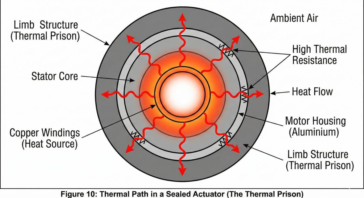
The thermal behavior of an actuator can be approximated using a lumped thermal model:
C_th × d(ΔT)/dt = P_loss(t) − ΔT/R_th
At steady state:
ΔT_ss = R_th × P_loss
Here, C_th represents thermal capacitance, R_th represents effective thermal resistance, P_loss represents total power loss, and ΔT represents temperature rise.
This simplified model highlights two important principles. First, short-term peak performance does not prove long-term thermal stability. Second, thermal performance depends on where heat is generated and how effectively it is transferred to the environment.
In a robot joint module, heat may originate from motor copper loss, motor iron loss, inverter switching and conduction loss, bearing friction, gearbox transmission loss, seals, lubrication, and electronic components. The housing, mounting flange, surrounding robot structure, and ambient environment then determine how effectively this heat can leave the actuator.
This is why two robot joint actuators with similar torque ratings can behave very differently in continuous operation.
Reduction Ratio Is a Trade-Off Between Torque Density, Backdrivability, and Dynamic Performance
Reduction ratio should be considered as a system-level design variable rather than an isolated specification.
A relatively low reduction ratio can provide better potential backdrivability and lower transmission ratio between motor-side and output-side motion, depending on the transmission architecture. This can be beneficial in applications that require force control, impedance control, or direct interaction with the environment. The trade-off is that the motor generally needs to provide more torque for the same output torque, which can increase motor size, current demand, and thermal requirements.
A higher reduction ratio can make it easier to obtain high output torque from a relatively compact motor and can reduce the load inertia reflected to the motor side. This can be useful for low-speed, high-torque operation and compact packaging. However, as the transmission ratio increases, the influence of transmission efficiency, friction, hysteresis, lost motion, torsional compliance, transmission error, and backdrivability can become increasingly important to system behavior.
Therefore, the correct question is not whether the reduction ratio should be as high as possible. The more useful engineering question is which reduction ratio can provide the required torque, speed, thermal performance, mechanical stiffness, and control characteristics within the available package.
Mechanical Stiffness and Transmission Nonlinearity Often Matter More Than the Nominal Ratio
Two actuators with the same nominal reduction ratio can have very different control performance. The difference may come from torsional stiffness, backlash, lost motion, friction, hysteresis, transmission error, bearing stiffness, preload, load distribution, manufacturing tolerances, and lubrication conditions.
This becomes especially important in high-precision robotic joints. A transmission with very low nominal backlash may still exhibit measurable elastic deformation and hysteresis under load. Conversely, a mechanically stiff transmission may provide better positioning stability while introducing other trade-offs such as mass, friction, manufacturing complexity, or cost.
For a robot joint actuator used in force control, the relationship between motor current and actual output torque can also become nonlinear. Motor current provides a useful estimate of motor electromagnetic torque, but output torque can differ because of transmission friction, elastic deformation, efficiency variation, and other mechanical effects.
Therefore, when a joint actuator is expected to perform high-quality force or impedance control, engineers should consider whether the system requires motor-side encoder feedback, output-side encoder feedback, a dual-encoder architecture, torque sensing, model-based friction compensation, or elastic deformation compensation.
The more demanding the application, the less useful it is to judge the actuator from motor torque alone.
Control Bandwidth Is Limited by Mechanical Dynamics as Well as the Controller
A robot joint actuator may have a high-speed servo drive, fast communication bus, and high-resolution encoder, but these features do not automatically produce high closed-loop bandwidth. The mechanical structure imposes its own limits.
A geared actuator can be approximated as a two-inertia system consisting of motor-side inertia, load-side inertia, transmission stiffness, and transmission damping.
A simplified elastic transmission relationship can be written as:
τ_s = K_s × (θ_m / i − q) + B_s × (θ̇_m / i − q̇)
where K_s is equivalent torsional stiffness, B_s is equivalent damping, θ_m is motor position, q is output position, and i is the reduction ratio.
The important point is not the formula itself. The important point is that finite transmission stiffness creates mechanical modes, including resonance and anti-resonance behavior.
If the desired control bandwidth approaches a significant mechanical resonance, simply increasing controller gains may make the system less stable rather than more responsive.
For this reason, robot joint module evaluation should consider encoder location, transmission stiffness, mechanical resonance frequency, damping, control-loop bandwidth, sampling frequency, current-loop bandwidth, and the structure of the position and velocity loops.
A controller cannot completely compensate for a mechanical structure whose usable bandwidth has already been limited by its physical dynamics.
Encoder Architecture Matters in a Robot Joint Module
Encoder configuration is often overlooked when comparing robot joint modules.
A motor-side encoder can provide high-resolution rotor position and velocity information. However, it does not directly measure the final output position after transmission deformation, backlash, hysteresis, and other mechanical effects.
An output-side encoder provides direct information about actual joint position. A dual-encoder configuration can therefore provide a different control architecture from a motor-only encoder and can help separate motor-side motion from output-side motion.
For applications requiring high positioning accuracy, low output error, or advanced compensation, engineers should ask a simple question: where is the position actually being measured?
This can be more important than simply asking how many encoder bits the system provides. High encoder resolution is useful only when the mechanical system and control architecture can make practical use of that resolution.
Bearing and Gear Life Should Be Design Constraints From the Beginning
Mechanical life should not be treated only as a final prototype validation item. For a robot joint actuator, output bearings can experience radial load, axial load, overturning moment, eccentric loading, impact loading, and preload effects.
Therefore, checking only nominal output torque may underestimate the actual bearing load.
Bearing Life Calculation
For rolling bearings, the classical basic rating life relationship is commonly expressed as:
L10 = (C/P)^p × 10⁶ revolutions
where C is the basic dynamic load rating, P is the equivalent dynamic bearing load, and p is 3 for ball bearings and 10/3 for roller bearings.
This is a basic rating-life calculation rather than a complete prediction of field life. Actual bearing life can also be affected by lubrication, contamination, reliability requirements, operating temperature, misalignment, internal load distribution, and other operating conditions.
For a compact robot joint module, this distinction is important because the motor may have sufficient torque while the output bearing is subjected to an external overturning moment that significantly changes its actual load condition.
Gear and Transmission Life
For cylindrical spur and helical gears, ISO 6336 provides a framework for calculating load capacity and evaluating several gear failure modes, including tooth flank contact stress and tooth-root bending strength.
However, ISO 6336 should not be treated as a universal calculation method for every robot transmission. Its scope is associated with cylindrical spur and helical gears, while harmonic, cycloidal/RV, and planetary transmissions require analysis appropriate to their specific architectures and design methods.
The general engineering principle remains the same: transmission life should be evaluated against the real load spectrum rather than a single nominal torque value. Frequent reversals, impact loads, thermal conditions, lubrication, load distribution, and manufacturing accuracy can all influence service life.
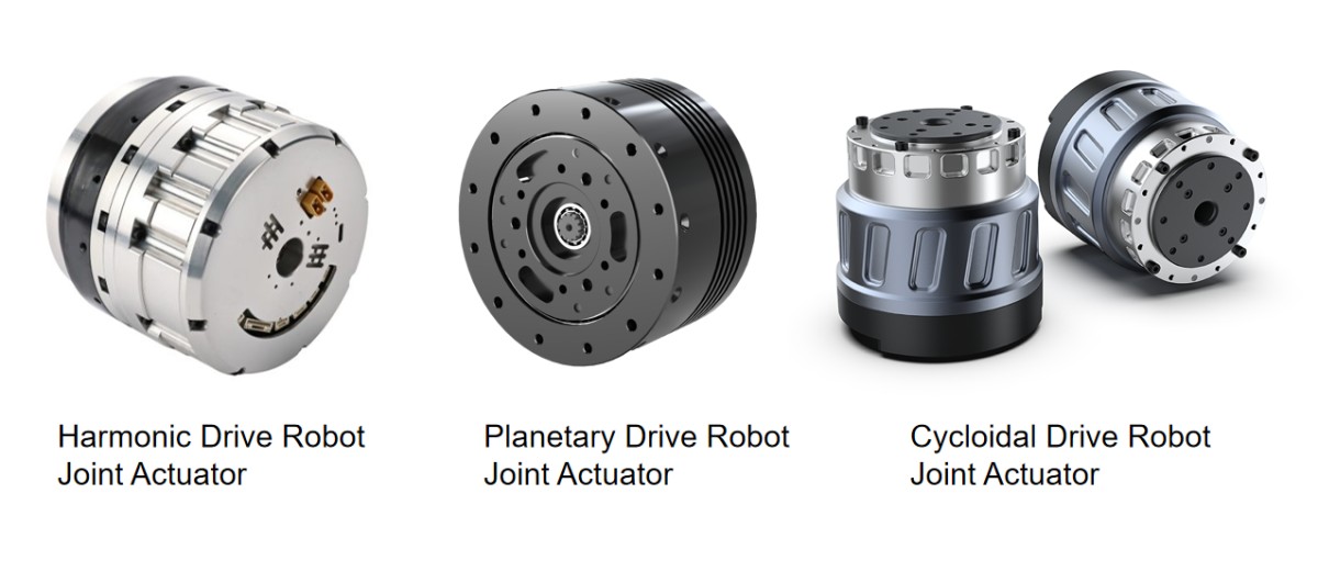
Harmonic, Planetary, and RV Transmissions Serve Different System Requirements
It is tempting to ask which transmission technology is better. For engineering selection, a more useful question is which transmission architecture best satisfies the application's mechanical, thermal, dynamic, and packaging constraints.
Harmonic Transmission
Harmonic transmission systems are attractive for robot joint actuators where compact packaging, high reduction ratios, low transmission backlash, and lightweight integration are important. They are widely considered for robotic arms, collaborative robots, humanoid robot joints, compact rotary actuators, and precision positioning mechanisms.
However, engineers should evaluate torsional stiffness, hysteresis, transmission efficiency, thermal behavior, shock loading, and service-life requirements rather than selecting a harmonic transmission based only on reduction ratio or nominal backlash.
Planetary Transmission
Planetary transmissions can provide a combination of efficiency, torque density, speed capability, scalable reduction ratios, manufacturing flexibility, and cost control. They can therefore be useful in robot joint actuators where the application requires a balance between dynamic response, torque capacity, efficiency, and service life.
Actual performance depends strongly on the planetary architecture, stage count, bearing arrangement, load sharing, gear quality, lubrication, and manufacturing accuracy.
RV and Cycloidal-Type Transmission
RV and related cycloidal transmission architectures are often considered where high rigidity, high load capacity, and resistance to external loads are important. They can be suitable for heavy industrial robots, large robotic arms, positioning systems, and high-load rotary mechanisms.
The trade-offs can include greater mechanical complexity, size, mass, manufacturing requirements, and cost.
The important point is that transmission technology should be selected according to the actual application envelope rather than according to a general assumption that one architecture is universally superior.
The Correct Robot Joint Actuator Selection Sequence
Instead of starting with a product catalog and working backward, a more robust process starts with the application requirements.
Step 1 — Define the Operating Envelope
The operating envelope should include peak torque, continuous torque, RMS torque, maximum speed, typical speed, acceleration and deceleration, load inertia, eccentricity, external radial and axial loads, overturning moment, duty cycle, ambient temperature, cooling conditions, positioning accuracy, repeatability, stiffness, backdrivability, and expected lifetime.
These parameters form the actual engineering requirement for the robot joint actuator.
Step 2 — Define the Reduction Ratio Range
Rather than immediately selecting a single reduction ratio, define a reasonable range and evaluate each candidate against motor speed, motor torque, reflected load inertia, output speed, transmission efficiency, thermal losses, backdrivability, mechanical stiffness, and resonance behavior.
The objective is not to find the ratio with the best individual specification. It is to find the range in which the entire system remains feasible.
Step 3 — Match the Motor, Transmission, Drive, and Thermal Path
A complete robot joint module should be evaluated as an integrated system.
The motor selection should consider torque constant, rotor inertia, winding resistance, maximum speed, continuous current, peak current, bus voltage, thermal resistance, and cooling conditions. The transmission should be evaluated for reduction ratio, efficiency, stiffness, lost motion, hysteresis, load capacity, life, lubrication, and temperature limits. The drive should be evaluated for current capability, bus voltage, control bandwidth, communication interface, encoder compatibility, thermal limits, and safety functions where required.
The mechanical housing and mounting interface should also be considered part of the thermal design because they can determine how efficiently heat is transferred away from the actuator.
Matching the motor and gearbox while ignoring the thermal path is a common reason for late-stage redesign.
Step 4 — Eliminate Weak System Architectures Before Comparing Cost
Once the basic requirements are defined, candidate robot joint actuators should first be screened against hard engineering constraints.
A candidate should be reconsidered if continuous operation exceeds its thermal capability, mechanical resonance is too close to the intended control bandwidth, bearing life is insufficient under the actual external load, transmission life does not cover the expected duty cycle, output stiffness is insufficient, lost motion is incompatible with the positioning requirement, backdrivability is unsuitable for the intended control mode, motor speed exceeds the available drive or bus-voltage capability, or the actuator cannot dissipate heat effectively within the robot structure.
Only after these constraints are satisfied does it make sense to compare dimensions, weight, cost, supply chain, manufacturing complexity, and integration time.
“It Runs” Does Not Mean the System Is Optimized
Many robot joint modules can move successfully during prototype testing. That proves that the basic function works, but it does not prove that the actuator is optimized for production.
Problems often emerge later. A prototype may run successfully while production variation becomes difficult to control. An unloaded joint may perform well while temperature rises excessively under load. A single joint may work correctly while multiple joints create power and thermal interactions. Low-speed positioning may remain stable while high-speed reversal excites vibration. Initial positioning accuracy may be good while lost motion or repeatability deteriorates after long-term operation.
These are system-level problems. They cannot always be solved simply by selecting a motor with a larger peak torque rating.
From Robot Joint Motor to Robot Joint Actuator: Think at the System Level
The distinction between a robot joint motor and a complete robot joint actuator is important.
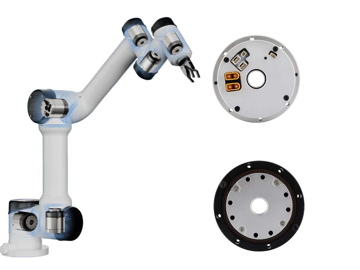
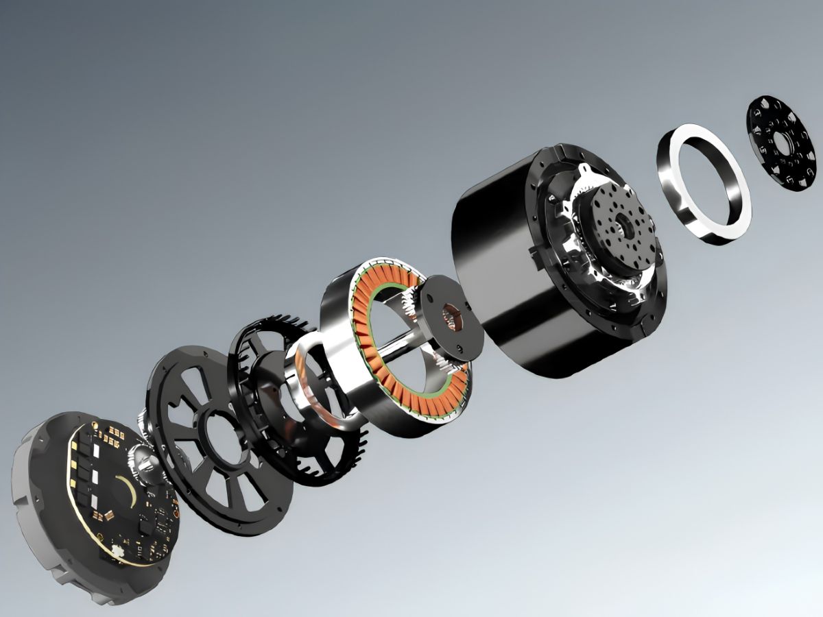
A robot joint motor primarily describes the motor element that generates electromagnetic torque. A robot joint actuator, by contrast, can integrate the motor, reduction mechanism, encoder system, bearings, drive electronics, brake, housing, thermal path, and control interface.
A robot joint module takes this integration concept further by packaging multiple functional elements into a mechanically installable joint assembly.
For robot manufacturers, this distinction matters because system performance depends on the integration of these components rather than the motor specification alone.
A high-torque motor cannot compensate for insufficient transmission stiffness. A high-resolution encoder cannot eliminate mechanical hysteresis. A large peak torque rating cannot solve inadequate thermal dissipation. A fast servo drive cannot remove a mechanical resonance that is fundamentally determined by the transmission and structure.
This is why the selection of a robotic joint actuator should begin with the desired system behavior rather than a single component specification.
Practical Robot Joint Module Selection Checklist
Project Definition Stage
Before selecting a product, confirm that the actual duty cycle has been defined and that peak, RMS, and continuous torque requirements are separated. Load inertia should include the end effector and tooling, while eccentric loads and external moments should also be included. Ambient temperature, cooling conditions, mechanical stiffness, positioning accuracy, repeatability, backdrivability, and expected service life should be established before comparing specific actuator models.
Concept Selection Stage
During concept selection, check whether the reduction ratio is compatible with motor speed and whether reflected load inertia has been evaluated. Motor current and bus-voltage margins should be sufficient, and continuous torque should be evaluated under the actual duty cycle rather than under an isolated catalog condition. Transmission stiffness, backlash or lost motion, efficiency, bearing life, and transmission life should all be considered against the real operating load.
Prototype Validation Stage
Prototype validation should include long-duration thermal testing, RMS torque validation, repeated peak-load testing, positive and negative direction reversal tests, output stiffness testing, positioning and repeatability testing under load, vibration and resonance testing, backdrivability testing where relevant, impact or shock testing where required, and long-cycle life testing.
These tests provide information that a product datasheet cannot fully capture.
Conclusion — Robot Joint Actuator Selection Is Ultimately About System Behavior
Inertia matching remains an important part of robot joint actuator design, but it should be treated as one engineering constraint within a larger system model.
The reduction ratio determines more than torque multiplication. The motor determines more than whether the joint can rotate. The transmission determines more than nominal backlash. The encoder determines more than resolution.
The complete actuator must simultaneously satisfy the load spectrum, torque, speed, thermal limits, mechanical stiffness, transmission nonlinearity, control bandwidth, bearing capacity, transmission life, packaging, and integration requirements.
When these constraints are evaluated together, the inertia ratio usually falls into a reasonable range as a consequence of the overall design. When the system is designed around inertia ratio alone, it is possible to obtain a mathematically attractive result that performs poorly in the real machine.
For engineers selecting a robot joint actuator, the real objective is therefore not to find the component with the most impressive individual specification. It is to build a joint system whose mechanical, electrical, thermal, and control characteristics remain balanced throughout the complete operating envelope.
The goal is not simply to make the joint move. The goal is to make the joint behave predictably, repeatedly, and reliably under the conditions for which the robot was designed.
Read More
Learn more about the story of HONPINE and industry trends related to precision transmission.
 What is robot joint actuator?How to Choose the Best Robot Rotary Joint Actuator?In core robot joint transmission solutions, planetary and harmonic rotary actuators each have their own strengths. Choosing the right type based on application requirements is essential to achieve the optimal balance between performance and cost.
 DD Motors VS Harmonic Rotary ActuatorsThis article provides an in-depth comparison between Direct Drive (DD) motors and harmonic rotary actuators, covering their transmission principles, advantages and disadvantages, and typical application fields.
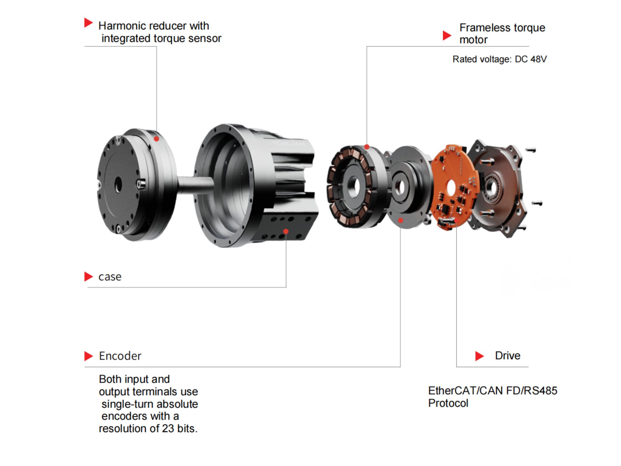
 OMG Ultra Compact Harmonic Drive Joint Module with Built-in Torque SensorHONPINE TCHL series harmonic drive joint module is a game-changing product that achieves disruptive improvements in multiple aspects such as lightweight design, integration level, and connection convenience. This article will analyze its revolutionary enhancements with you.
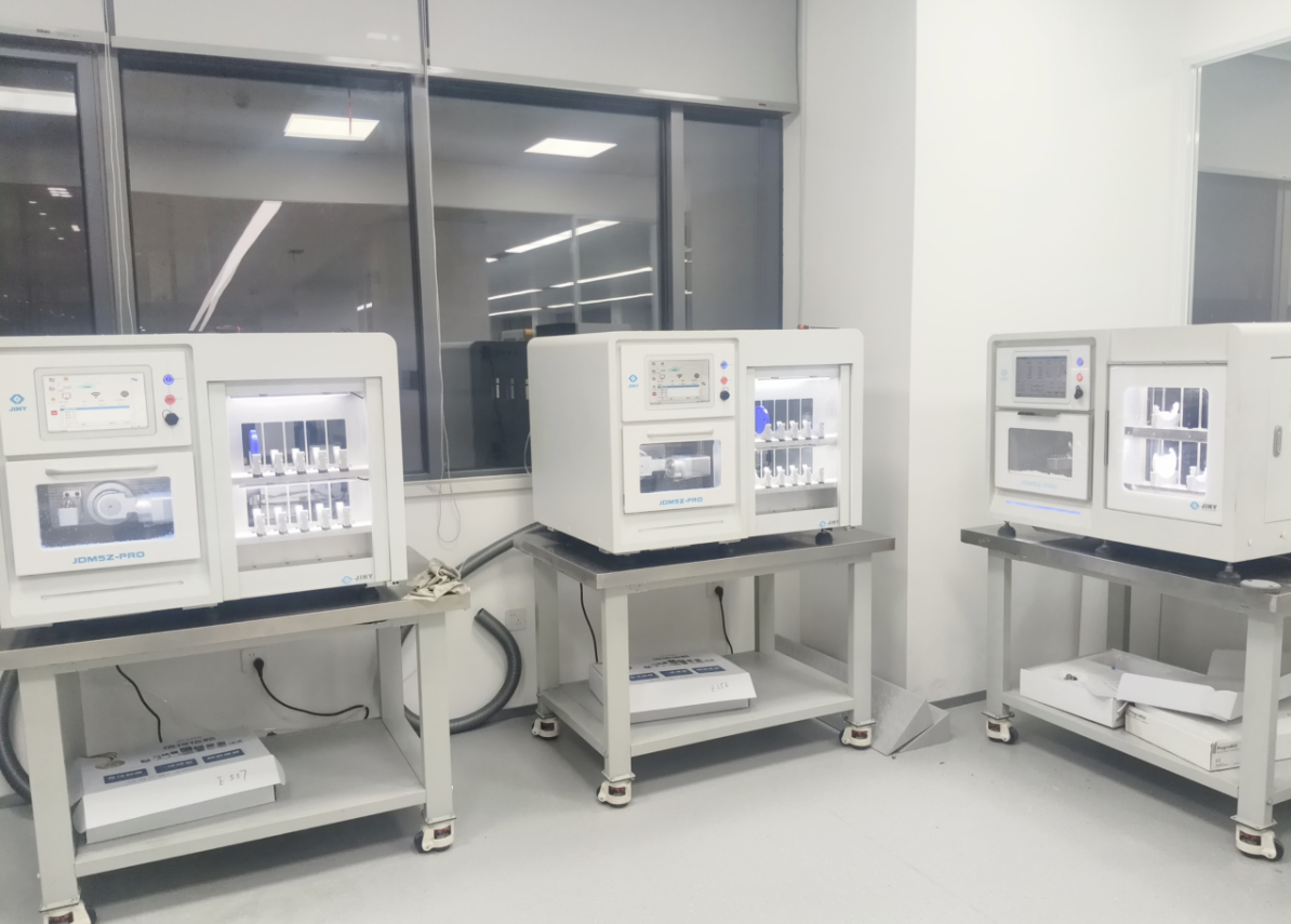
 The Role of Harmonic Drive Gears in Achieving 5–10 μm Accuracy in Dental Milling MachinesA dental milling machine is a CNC machining system used to directly process digital dental models into restorations such as crowns, bridges, veneers, inlays, and implant abutments. Dental milling machines require far higher operational accuracy and motion stability than ordinary equipment. This article explains how harmonic drive gear help dental milling machines achieve stable, continuous, and controllable operation.
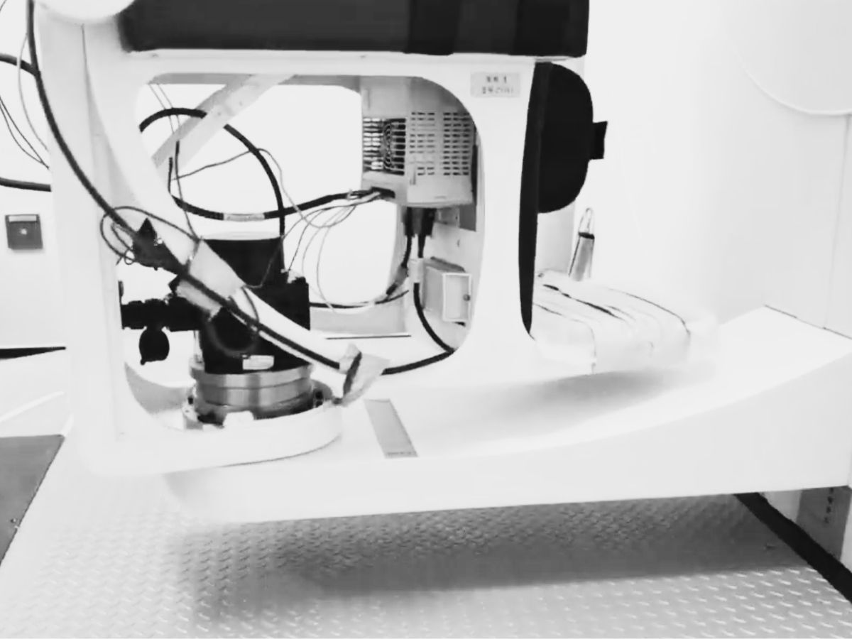
 Why Are Harmonic Rotary Actuators Perfect for Medical Equipment?Harmonic rotary actuators (typically integrated systems consisting of a harmonic drive reducer, frameless torque motor, encoder, and optional brake) are regarded as key components in medical equipment. The core reason is that they simultaneously meet the most stringent medical requirements for precision, compact size, safety, and controllability. The following explanation is structured from three perspectives: technical characteristics, application scenarios, and medical value.
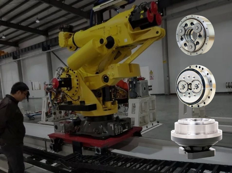
 High-Precision RV Reducers Perfectly Matched for Walking RobotsThe walking axis of a robot is a core component for power transmission and support. RV reducers provide extremely high rigidity, precision, and torque while maintaining a compact size and exceptional reliability, making them an ideal match for the demanding requirements of walking robot joints in terms of load capacity, impact resistance, and precision.
 Hollow Robot Joint Module: Why Cable Routing Matters in Robotic Joints?A hollow robot joint module provides an internal passage for power cables, signal lines, pneumatic tubes, and other end-effector connections. Compared with external cable routing, a hollow joint module can help reduce cable exposure, improve system integration, and create a cleaner motion path for robotic arms. This article explains why internal cable routing matters in robotic joints and what to consider when selecting a hollow joint module for robotic applications.
 Robot Joint Actuator Selection: From Inertia Matching to System-Level OptimizationSelecting a robot joint actuator is not simply a matter of matching motor torque or achieving a suitable inertia ratio. In a real robotic system, reduction ratio, load spectrum, thermal performance, mechanical stiffness, transmission nonlinearity, encoder architecture, control bandwidth, and service life all interact to determine the final result. A joint may meet its peak torque requirement and still experience vibration, overheating, positioning errors, or premature wear in real operation. This article examines the engineering logic behind robot joint actuator selection and explains why moving from single-parameter matching to system-level optimization can lead to more reliable and predictable robotic joint performance.
 HONPINE HAG Robot Joint Module Undergoing Pre-Shipment InspectionThe HONPINE HAG Robot Joint Module is currently undergoing pre-shipment inspection before delivery.
 How to Choose a Small Harmonic Actuator?HONPINE Series 11 small harmonic actuators provide a compact, high-performance rotary motion solution for precision automation applications. Available with hollow or solid shafts, 48V or 220V options, optional brakes, absolute encoders, and different reduction ratios, the Series 11 is designed for applications requiring compact dimensions, controlled torque, and precise positioning.
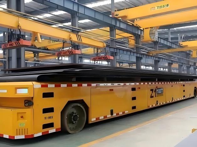
 How to Choose a Wheel Motor for a Heavy-Duty AGV? Key Challenges from Dynamic Loads to 120-Ton AGV Drive Wheel SystemsSelecting a Heavy-Duty AGV Wheel Motor is more than matching motor power or rated torque to the vehicle's payload. As AGVs move from conventional material handling to multi-ton and even 120-ton-class applications, the drive wheel system must handle dynamic loads, acceleration, braking, turning forces, traction, and long-term mechanical stress. The actual challenge lies in matching wheel load capacity, wheel-end torque, gearbox performance, steering architecture, suspension, and chassis design under real operating conditions. This article examines the key challenges of Heavy-Duty AGV Wheel Motor selection and explains how Steering Drive Wheels and Differential Drive Wheels can be evaluated for different heavy-duty AGV applications.
 DD Motor Servo System: How to Understand Mechanical Resonance and Solve Machine Vibration?This article explains the relationship between DD motor servo tuning, mechanical resonance, and servo bandwidth in direct drive motion systems. It examines why vibration and instability can occur even after repeated servo parameter adjustments, and explains how mechanical stiffness, moving mass, bearing conditions, load distribution, and structural geometry affect resonance frequency. The article also compares approaches for high- and low-frequency resonance, explains when digital notch filtering can be effective, and provides a practical tuning strategy for engineers working with DD motors, direct drive torque motors, and linear motors.
Double Click
We provide harmonic drive reducer,planetary reducer,robot joint motor,robot rotary actuators,RV gear reducer,robot end effector,dexterous robot hand
 What is robot joint actuator?How to Choose the Best Robot Rotary Joint Actuator?In core robot joint transmission solutions, planetary and harmonic rotary actuators each have their own strengths. Choosing the right type based on application requirements is essential to achieve the optimal balance between performance and cost.
 DD Motors VS Harmonic Rotary ActuatorsThis article provides an in-depth comparison between Direct Drive (DD) motors and harmonic rotary actuators, covering their transmission principles, advantages and disadvantages, and typical application fields.
 OMG Ultra Compact Harmonic Drive Joint Module with Built-in Torque SensorHONPINE TCHL series harmonic drive joint module is a game-changing product that achieves disruptive improvements in multiple aspects such as lightweight design, integration level, and connection convenience. This article will analyze its revolutionary enhancements with you.
 Hollow Robot Joint Module: Why Cable Routing Matters in Robotic Joints?A hollow robot joint module provides an internal passage for power cables, signal lines, pneumatic tubes, and other end-effector connections. Compared with external cable routing, a hollow joint module can help reduce cable exposure, improve system integration, and create a cleaner motion path for robotic arms. This article explains why internal cable routing matters in robotic joints and what to consider when selecting a hollow joint module for robotic applications.
 Robot Joint Actuator Selection: From Inertia Matching to System-Level OptimizationSelecting a robot joint actuator is not simply a matter of matching motor torque or achieving a suitable inertia ratio. In a real robotic system, reduction ratio, load spectrum, thermal performance, mechanical stiffness, transmission nonlinearity, encoder architecture, control bandwidth, and service life all interact to determine the final result. A joint may meet its peak torque requirement and still experience vibration, overheating, positioning errors, or premature wear in real operation. This article examines the engineering logic behind robot joint actuator selection and explains why moving from single-parameter matching to system-level optimization can lead to more reliable and predictable robotic joint performance.
 How to Choose a Small Harmonic Actuator?HONPINE Series 11 small harmonic actuators provide a compact, high-performance rotary motion solution for precision automation applications. Available with hollow or solid shafts, 48V or 220V options, optional brakes, absolute encoders, and different reduction ratios, the Series 11 is designed for applications requiring compact dimensions, controlled torque, and precise positioning.
 How to Choose a Wheel Motor for a Heavy-Duty AGV? Key Challenges from Dynamic Loads to 120-Ton AGV Drive Wheel SystemsSelecting a Heavy-Duty AGV Wheel Motor is more than matching motor power or rated torque to the vehicle's payload. As AGVs move from conventional material handling to multi-ton and even 120-ton-class applications, the drive wheel system must handle dynamic loads, acceleration, braking, turning forces, traction, and long-term mechanical stress. The actual challenge lies in matching wheel load capacity, wheel-end torque, gearbox performance, steering architecture, suspension, and chassis design under real operating conditions. This article examines the key challenges of Heavy-Duty AGV Wheel Motor selection and explains how Steering Drive Wheels and Differential Drive Wheels can be evaluated for different heavy-duty AGV applications.
 DD Motor Servo System: How to Understand Mechanical Resonance and Solve Machine Vibration?This article explains the relationship between DD motor servo tuning, mechanical resonance, and servo bandwidth in direct drive motion systems. It examines why vibration and instability can occur even after repeated servo parameter adjustments, and explains how mechanical stiffness, moving mass, bearing conditions, load distribution, and structural geometry affect resonance frequency. The article also compares approaches for high- and low-frequency resonance, explains when digital notch filtering can be effective, and provides a practical tuning strategy for engineers working with DD motors, direct drive torque motors, and linear motors.
 Why Do Industrial Robots and Heavy-Duty Equipment Prefer Dual-Disc RV Reducers?Many engineers have the same question when they first look inside an RV reducer: if a single cycloidal disc can already achieve speed reduction, why do industrial robot RV reducers almost always use two discs? The additional disc increases the number of components, assembly complexity, and manufacturing cost, so its purpose deserves a closer look. The answer is not simply a higher reduction ratio. A dual-disc RV reducer is designed to improve the overall mechanical behavior of the transmission through better force balance, load sharing, backlash control, torsional stiffness, and long-term reliability. In this article, we use an RV reducer assembly model and motion simulation to examine these mechanisms and explain why the dual-disc architecture is widely used in industrial robots, machine tools, rotary tables, and other heavy-duty precision transmission systems.
 Small Size Harmonic Drive Reducer: Advantages, Applications and Selection GuideSmall size harmonic drive reducer for compact precision motion systems, offering high reduction ratio, near-zero backlash, low weight and accurate transmission.
 High Precision Harmonic Drive Robot Joint Actuator Solution for Robotic ElbowsThe robotic elbow joint plays a critical role in arm flexion, posture adjustment, and end-effector positioning. As humanoid robots, collaborative robots, and robotic arms become more capable, elbow actuators need to deliver high torque and precise motion within increasingly limited installation spaces. A high precision harmonic drive robot joint actuator integrates the harmonic reducer, motor, encoder, brake, and drive system into a compact unit, providing low backlash, high stiffness, high torque density, and accurate motion control. In this article, HONPINE introduces three joint actuator series suitable for robotic elbow applications, covering different requirements for size, torque, speed, precision, and integration.
 Explosion-Proof Robot Joint Solution for Chemical Inspection Quadruped Robots: Planetary Joint Actuator with Up to 500 N·m Peak TorqueIn petrochemical, mining, power, and other hazardous environments, inspection robots are moving beyond simple monitoring toward practical operations such as tool handling, equipment inspection, and emergency response. This shift places higher demands on robot joint actuators, particularly in explosion protection, torque output, thermal management, environmental resistance, and mobility. HONPINE's explosion-proof robot joint actuator is designed for quadruped inspection robots and other hazardous-environment robotic platforms, integrating high-load planetary transmission with explosion-proof design and reliable motion performance. With up to 500 N·m peak torque per joint, optional IP67 protection, and Ex db IIB T4 Gb certification, the solution is designed to support demanding robotic applications in high-risk industrial environments.