








Hollow Rotary Platform Motor Matching: A Complete Guide
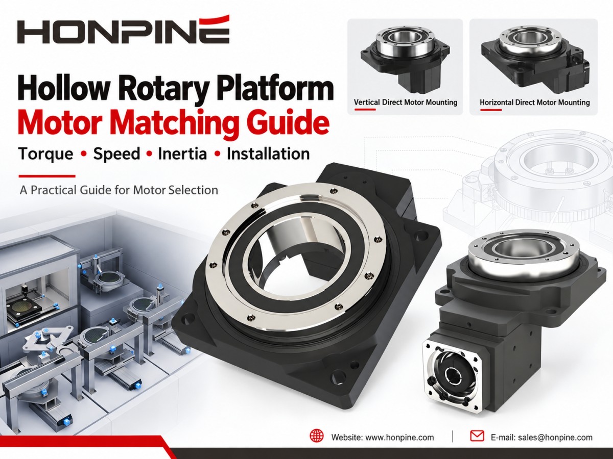
Choosing the right motor for a hollow rotary platform starts with understanding your load, speed, and positioning requirements. This guide compares servo, stepper, and brushless DC motors, explains torque, speed, inertia, and accuracy matching, and explores space-saving mounting options. Use it to identify a suitable motor and platform combination for your automation project.
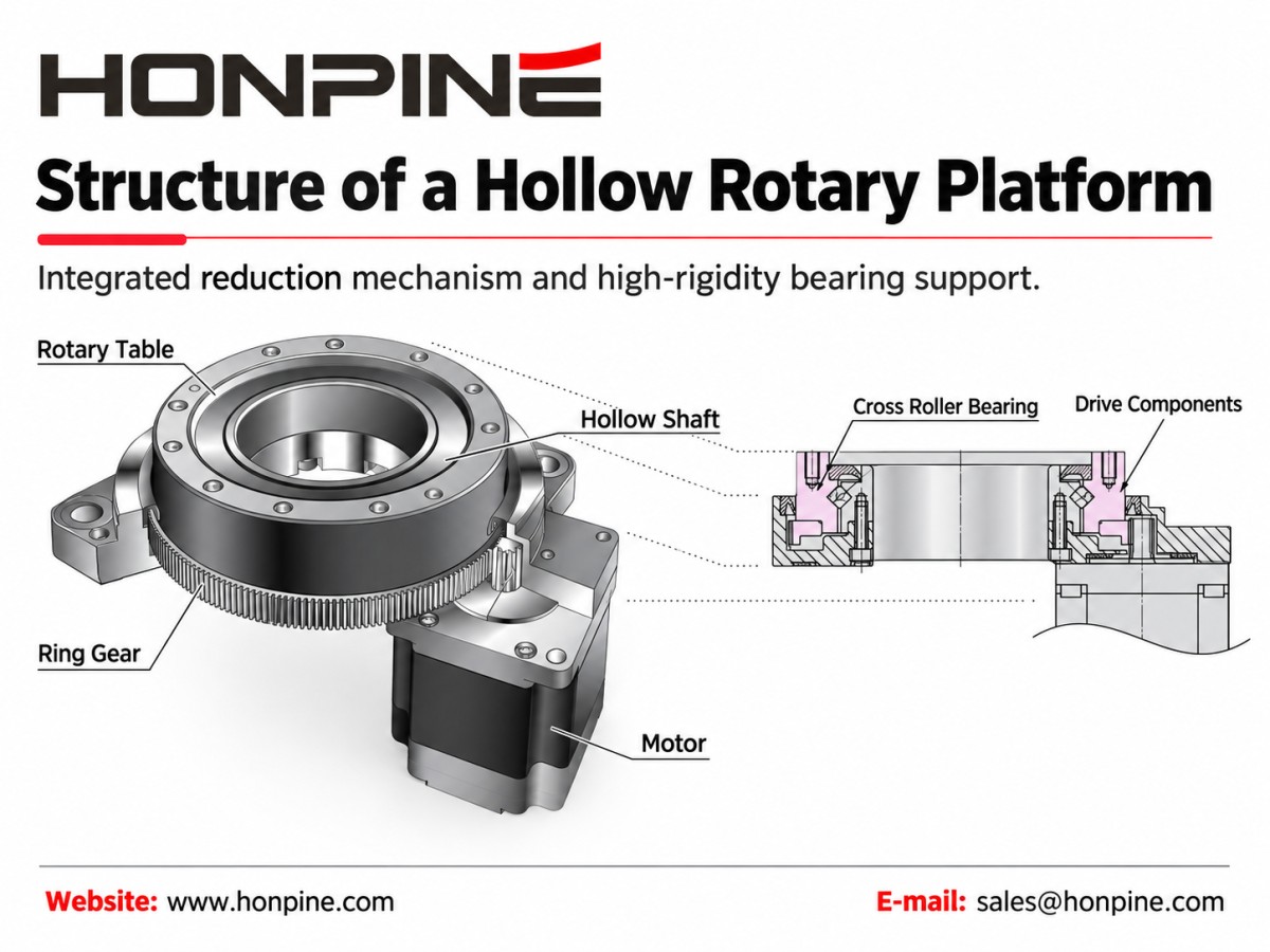
A hollow rotary platform is a precision rotary positioning device with a central through-hole. A typical geared design combines a reduction mechanism with a rigid, bearing-supported output table. Some designs use crossed roller bearings to support high-rigidity rotary motion, while the hollow center provides space for cables, pneumatic tubing, or other components.
As the platform’s power source, the motor directly influences motion performance, including response speed, acceleration capability, and positioning behavior. However, selecting a suitable motor requires more than comparing power ratings. The motor, drive, transmission, and load must be evaluated as a complete system.
1. Motor Types and Selection Guidelines
Hollow rotary platforms can be paired with different motor types depending on the application’s motion requirements and the platform’s mechanical compatibility. Servo motors, stepper motors, and brushless DC motors each offer different advantages.
1.1 Servo Motors for High-Precision and High-Dynamic Applications
Performance Characteristics
Servo systems use feedback to compare commanded motion with actual motor motion and adjust the output accordingly. This makes them suitable for applications requiring responsive control of position, speed, and torque.
Actual performance depends on the selected motor, encoder, drive settings, transmission, and mechanical structure. A high-resolution encoder alone does not guarantee high positioning accuracy at the platform output.
Suitable Applications
Servo motors are a strong option for precision assembly, semiconductor handling, vision inspection, and other applications involving demanding positioning requirements or frequent acceleration and deceleration.
When selecting the motor and drive, define the required cycle time, acceleration, and settling performance. Do not assume that every servo system will deliver the same accuracy or response speed.
1.2 Stepper Motors for Cost-Effective Positioning and Indexing
Performance Characteristics
Traditional stepper motors convert command pulses into incremental angular movement and can operate without position feedback. They offer a relatively simple and economical approach to positioning.
However, insufficient torque or unsuitable acceleration settings can cause missed steps. Microstepping can improve motion smoothness, but actual positioning accuracy still depends on the motor, drive, load, and operating conditions.
Closed-loop stepper systems are also available for applications that require feedback.
Suitable Applications
Stepper motors are worth considering for conventional assembly stations, rotary indexing, material handling, and packaging equipment where the required speed and motion profile are compatible with the motor.
During selection, check the available torque at the intended operating speed rather than relying only on the motor’s holding torque.
1.3 Brushless DC Motors for Variable-Speed Rotary Motion
Performance Characteristics
Brushless DC motor-and-drive systems are useful for controlled rotary motion across a range of speeds. Their available functions vary: some focus on speed regulation, while others also support positioning and torque limiting.
Motor efficiency, speed range, and control capabilities should be evaluated using the specifications of the selected motor-and-drive combination.
Suitable Applications
Consider a brushless DC motor when the application prioritizes stable rotational speed or adjustable-speed operation.
A high-speed motor does not automatically make the complete platform suitable for high-speed operation. The platform’s permissible input speed, output speed, lubrication requirements, and continuous-duty capability must also be checked.
2. Core Principles for Matching Motors with Hollow Rotary Platforms
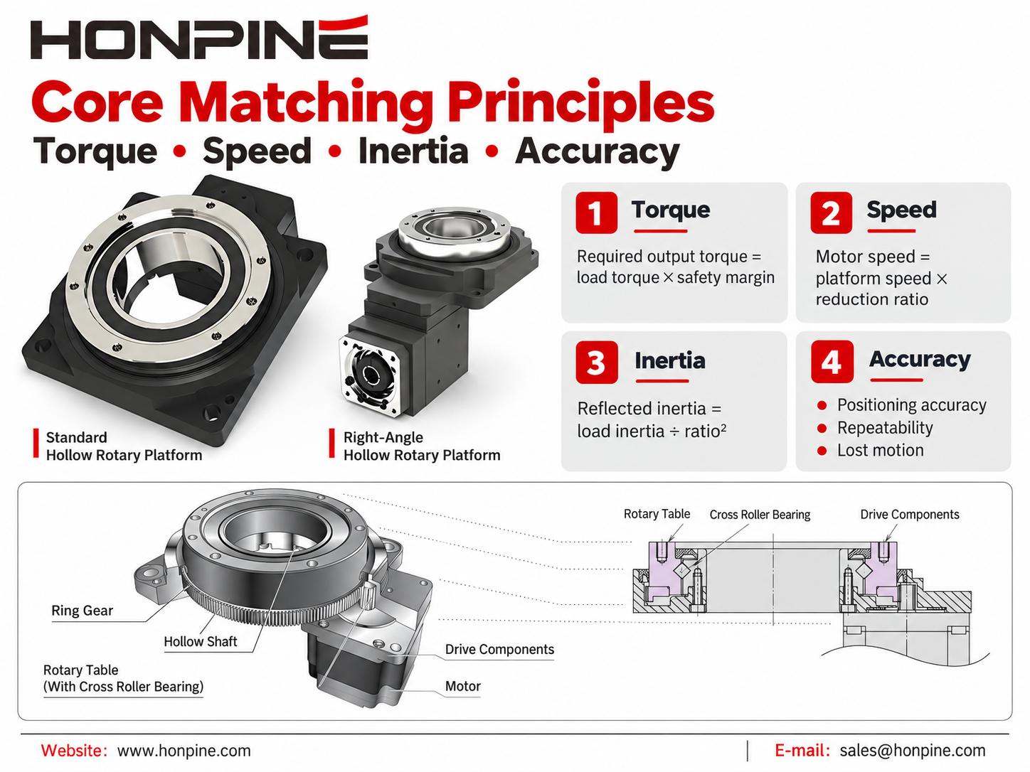
2.1 Torque Matching
The motor must provide enough torque to overcome the load and accelerate or decelerate the rotating assembly.
Calculate both the steady load torque and the acceleration torque. Include an appropriate safety margin based on uncertainty in friction, load variation, operating conditions, and the application’s duty cycle.
For a preliminary transmission check:
Transmitted output torque ≈ Motor input torque × Reduction ratio × Transmission efficiency
This relationship does not replace a complete calculation of acceleration demand, internal inertia, and duty cycle. The resulting output torque must also remain within the platform’s permissible torque limits.
For servo systems, verify that the required peak torque stays within the permitted intermittent operating range. The cycle’s root-mean-square, or RMS, torque must remain within the motor’s continuous-duty capability under the relevant operating conditions.
The permitted duration of peak torque should also be checked.
2.2 Speed Matching
Start with the required platform output speed and the reduction ratio:
Required motor speed = Required platform output speed × Reduction ratio
For example, a platform output speed of 100 rpm with a 10:1 reduction ratio requires a motor speed of 1,000 rpm.
Check the motor’s available torque at that speed, together with the platform’s permissible input and output speeds.
For indexing applications, the average rotational speed is not enough for motor selection. The actual motion profile may require a much higher maximum speed during each movement, particularly when the available acceleration and deceleration time is short.
Select the motor and platform using the complete motion cycle rather than the motor’s rated power alone.
2.3 Inertia Matching
Inertia matching compares the load inertia reflected to the motor shaft with the motor’s rotor inertia.
For an ideal reduction stage:
Reflected output-side load inertia = Output-side load inertia ÷ Reduction ratio²
Then calculate:
Inertia ratio = Total reflected load inertia ÷ Motor rotor inertia
Include the relevant platform, coupling, and transmission inertia in the final calculation.
For example, a 10:1 reduction ratio reduces the output-side load inertia reflected to the motor shaft to 1/100 of its original value, before adding the other relevant system inertias.
A load-to-motor inertia ratio such as 1:1 to 10:1 can serve as an initial design reference for some servo applications, but it is not a universal requirement or limit.
The acceptable ratio depends on mechanical rigidity, acceleration requirements, drive tuning, and the selected motor-and-drive system.
2.4 Accuracy Matching
Evaluate the motor’s feedback resolution alongside the positioning requirements of the complete platform.
Higher encoder resolution provides finer feedback information, but output positioning accuracy also depends on transmission accuracy, lost motion, mechanical stiffness, load conditions, and control performance.
Request separate specifications for:
Positioning accuracy: How closely the actual output position matches the commanded position.
Repeatability: How consistently the platform returns to the same position under specified conditions.
Lost motion: Motion that is not immediately transferred to the output, particularly when the direction changes.
For demanding applications, verify performance with the intended load, movement direction, and settling time.
Specify rotary positioning requirements in angular units, such as degrees or arcseconds. A linear positioning tolerance should only be stated with a defined working radius.
2.5 Mechanical Installation and Interface Compatibility
Check the complete motor-to-platform interface before ordering.
Compare the motor shaft diameter and length, flange dimensions, mounting-hole pattern, locating features, and coupling arrangement with the platform’s installation drawing.
A motor with a suitable torque rating is not necessarily a mechanical fit.
Correct shaft alignment and a suitable coupling arrangement are important for reliable transmission. Installation errors can introduce additional stress, vibration, and premature wear.
Also consider environmental protection requirements, cable-exit direction, connector clearance, and access for installation and maintenance.
3. Typical Motor and Platform Combinations
3.1 Precision Assembly and Inspection: Servo Motor + Hollow Rotary Platform
For precision assembly or inspection projects, begin by evaluating a servo-driven hollow rotary platform against the required positioning accuracy, load inertia, and cycle time.
This combination is suitable for applications requiring responsive motion control, frequent starting and stopping, and controlled acceleration and deceleration.
However, a servo motor does not automatically eliminate mechanical backlash or transmission errors. Prioritize the complete system’s performance rather than relying only on the motor’s power rating or encoder specification.
Verify the motor, drive, coupling, and platform together under the intended operating conditions.
3.2 Conventional Assembly and Indexing: Stepper Motor + Hollow Rotary Platform
For routine indexing and assembly operations, evaluate whether a stepper-driven platform can meet the required speed, acceleration, and positioning performance.
This combination can provide an economical solution when the motion requirements are moderate and sufficient torque is available throughout the operating range.
A closed-loop stepper configuration is another option when feedback is desirable while retaining stepper-based motion control.
For reliable operation, confirm the available running torque and use an acceleration profile suitable for the load.
3.3 Speed-Controlled Rotation: Brushless DC Motor + Compatible Hollow Rotary Platform
For an application focused on controlled rotational speed, evaluate a brushless DC motor-and-drive package together with a compatible hollow rotary platform.
Confirm the required speed range, continuous operating duty, available torque, and control functions.
Where accurate stopping positions are also required, verify that the selected drive supports the necessary positioning operation.
The platform must be rated for the intended rotational speed and operating duration. Motor speed capability should never be treated as the operating limit of the complete rotary assembly.
4. How to Reduce Hollow Rotary Platform Installation Space?
4.1 Use the Hollow Center for Cable and Tube Routing
The central opening can accommodate wiring, pneumatic tubing, or other services that need to pass through the rotary assembly.
This can simplify routing compared with taking every connection around the outside of the platform.
During layout planning, check the usable bore diameter and reserve sufficient space for the actual cable and tube bundle.
Plan the routing together with the required rotation range. The hollow opening provides a routing path, but it does not automatically prevent cables or tubes from twisting.
4.2 Consider Horizontal or Right-Angle Motor Mounting
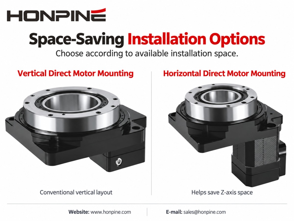
When vertical clearance is limited, compare horizontally mounted or right-angle motor configurations with a conventional vertical arrangement.
A suitable horizontal or right-angle configuration can reduce the space required along the Z-axis, making it useful for equipment with limited installation height.
However, reducing vertical height may increase the horizontal footprint.
Compare the complete installed dimensions, including the platform, motor, connectors, cable bend radius, and maintenance clearances.
Select the arrangement that fits the equipment layout as a whole rather than evaluating the platform body alone.
4.3 Choose Cable Management According to the Rotation Pattern
For limited-angle movement, such as 90° back-and-forth indexing, a suitable flexible cable or tube arrangement may avoid the need for a slip ring.
The routing must still accommodate the movement without excessive bending, twisting, tension, or interference with nearby components.
For continuous rotation where electrical power or signals must pass between stationary and rotating components, an electrical slip ring is a common solution.
If compressed air must also cross the rotating interface, a pneumatic rotary union or combined pneumatic–electrical assembly may be required.
A single 360° move followed by a return is not the same as continuous rotation in one direction.
Choose the cable-management arrangement according to the actual motion pattern, operating frequency, and services that must cross the rotating interface—not the rotation angle alone.
5. Final Selection Checklist
Before choosing a motor and hollow rotary platform, define the load mass and dimensions, output speed, indexing angle, acceleration time, duty cycle, positioning requirements, and available installation space.
Use these requirements to compare candidate combinations. Check peak and continuous torque, motor speed, reflected load inertia, mechanical interfaces, and cable routing.
For demanding applications, verify the complete assembly against the intended motion profile before finalizing the selection.
The right combination is not necessarily the motor with the highest power or the platform with the largest size. It is the combination that meets the application’s performance requirements while fitting the available space and operating conditions.
Planning a rotary automation project? Contact HONPINE with your load details, required output speed, motion cycle, and installation dimensions to discuss a suitable hollow rotary platform and motor combination.
Read More
Learn more about the story of HONPINE and industry trends related to precision transmission.
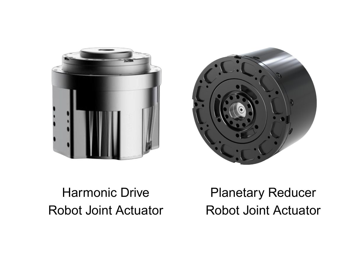
 What is robot joint actuator?How to Choose the Best Robot Rotary Joint Actuator?In core robot joint transmission solutions, planetary and harmonic rotary actuators each have their own strengths. Choosing the right type based on application requirements is essential to achieve the optimal balance between performance and cost.
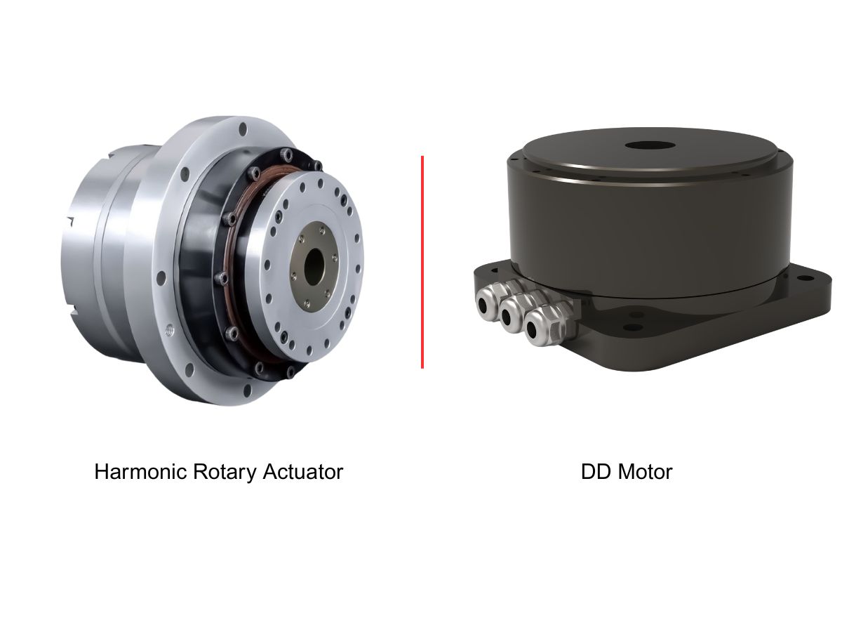
 DD Motors VS Harmonic Rotary ActuatorsThis article provides an in-depth comparison between Direct Drive (DD) motors and harmonic rotary actuators, covering their transmission principles, advantages and disadvantages, and typical application fields.
 OMG Ultra Compact Harmonic Drive Joint Module with Built-in Torque SensorHONPINE TCHL series harmonic drive joint module is a game-changing product that achieves disruptive improvements in multiple aspects such as lightweight design, integration level, and connection convenience. This article will analyze its revolutionary enhancements with you.
 The Role of Harmonic Drive Gears in Achieving 5–10 μm Accuracy in Dental Milling MachinesA dental milling machine is a CNC machining system used to directly process digital dental models into restorations such as crowns, bridges, veneers, inlays, and implant abutments. Dental milling machines require far higher operational accuracy and motion stability than ordinary equipment. This article explains how harmonic drive gear help dental milling machines achieve stable, continuous, and controllable operation.
 Why Are Harmonic Rotary Actuators Perfect for Medical Equipment?Harmonic rotary actuators (typically integrated systems consisting of a harmonic drive reducer, frameless torque motor, encoder, and optional brake) are regarded as key components in medical equipment. The core reason is that they simultaneously meet the most stringent medical requirements for precision, compact size, safety, and controllability. The following explanation is structured from three perspectives: technical characteristics, application scenarios, and medical value.
 High-Precision RV Reducers Perfectly Matched for Walking RobotsThe walking axis of a robot is a core component for power transmission and support. RV reducers provide extremely high rigidity, precision, and torque while maintaining a compact size and exceptional reliability, making them an ideal match for the demanding requirements of walking robot joints in terms of load capacity, impact resistance, and precision.
 AGV Suspension: Should You Choose a Balance Beam or a Spring-Loaded Steering Drive Unit?Choosing an AGV suspension system starts with the vehicle’s load range and floor conditions. Balance beams and spring-loaded steering drive units offer different approaches to maintaining wheel contact and managing wheel loads. This HONPINE guide compares both options and explains how to evaluate traction, suspension travel, installation space, and maintenance before choosing a configuration.
 Hollow Rotary Platform Motor Matching: A Complete GuideSelecting the right motor for a hollow rotary platform is essential for achieving precise positioning, stable operation, and efficient automation. This guide explains how to match servo motors, stepper motors, and brushless DC motors with hollow rotary platforms based on torque, speed, inertia, accuracy, and installation requirements. Explore practical motor selection guidelines, typical application combinations, and space-saving mounting solutions to find the right configuration for your automation project.
 Can Robots Feel Touch? HONPINE HAG Force-Controlled Harmonic Robot Joint MotorsCan robots respond to a gentle touch? The HONPINE HAG robot joint motor with torque sensor combines a harmonic reducer, integrated torque sensing, and closed-loop control to detect external forces and support smooth, compliant motion. In this article, HONPINE founder Allen Li demonstrates the module's response to light contact and hand-guided movement, explains its key force-control technologies, and shares the vision behind joint modules designed for practical industrial robotics.
 Does a Higher Gearbox Ratio Mean More Torque? Planetary, Harmonic, and RV Gearboxes ExplainedDoes a higher gearbox ratio mean more torque? This engineering guide explains the relationship between gearbox ratio, output torque, and output speed, and compares planetary gearboxes, harmonic gearboxes, and RV gearboxes. Learn why reduction ratio alone cannot determine gearbox torque capacity, efficiency, dynamic response, precision, or service life, and what engineers should consider when selecting a gearbox for robotics, CNC machines, servo systems, and industrial motion control.
 High-Precision Hollow Harmonic Rotary Actuator for CNC Machines and Heavy-Duty Rotary AxesHONPINE 58 Series Hollow Harmonic Rotary Actuator is designed for CNC rotary tables, precision rotary axes, laser processing equipment, and heavy-duty rotary positioning applications. With a 50 mm hollow bore, up to 2,722 N·m peak torque, integrated crossed roller bearing, multi-turn absolute encoder options, positioning accuracy below 30 arcsec, and repeat positioning accuracy below 5 arcsec, it combines high torque capacity with precision rotary motion and flexible mechanical integration.
 How Does the HONPINE JRM Planetary Robot Joint Module Address Temperature Rise in Continuous Operation?HONPINE JRM planetary robot joint modules are designed for long-duration and high-load robotic operation. This article examines how motor electromagnetic optimization, high-efficiency planetary transmission, GaN-based drive technology, and system-level low-loss design help control temperature rise. Using the C6345 planetary robot joint module as a test example, HONPINE also presents full-load thermal validation under continuous operation, including motor efficiency up to 92%, planetary gearbox efficiency up to 97%, and a final equilibrium temperature of 61.42°C at a 25°C ambient temperature.
Double Click
We provide harmonic drive reducer,planetary reducer,robot joint motor,robot rotary actuators,RV gear reducer,robot end effector,dexterous robot hand
 What is robot joint actuator?How to Choose the Best Robot Rotary Joint Actuator?In core robot joint transmission solutions, planetary and harmonic rotary actuators each have their own strengths. Choosing the right type based on application requirements is essential to achieve the optimal balance between performance and cost.
 DD Motors VS Harmonic Rotary ActuatorsThis article provides an in-depth comparison between Direct Drive (DD) motors and harmonic rotary actuators, covering their transmission principles, advantages and disadvantages, and typical application fields.
 OMG Ultra Compact Harmonic Drive Joint Module with Built-in Torque SensorHONPINE TCHL series harmonic drive joint module is a game-changing product that achieves disruptive improvements in multiple aspects such as lightweight design, integration level, and connection convenience. This article will analyze its revolutionary enhancements with you.
 AGV Suspension: Should You Choose a Balance Beam or a Spring-Loaded Steering Drive Unit?Choosing an AGV suspension system starts with the vehicle’s load range and floor conditions. Balance beams and spring-loaded steering drive units offer different approaches to maintaining wheel contact and managing wheel loads. This HONPINE guide compares both options and explains how to evaluate traction, suspension travel, installation space, and maintenance before choosing a configuration.
 Hollow Rotary Platform Motor Matching: A Complete GuideSelecting the right motor for a hollow rotary platform is essential for achieving precise positioning, stable operation, and efficient automation. This guide explains how to match servo motors, stepper motors, and brushless DC motors with hollow rotary platforms based on torque, speed, inertia, accuracy, and installation requirements. Explore practical motor selection guidelines, typical application combinations, and space-saving mounting solutions to find the right configuration for your automation project.
 Can Robots Feel Touch? HONPINE HAG Force-Controlled Harmonic Robot Joint MotorsCan robots respond to a gentle touch? The HONPINE HAG robot joint motor with torque sensor combines a harmonic reducer, integrated torque sensing, and closed-loop control to detect external forces and support smooth, compliant motion. In this article, HONPINE founder Allen Li demonstrates the module's response to light contact and hand-guided movement, explains its key force-control technologies, and shares the vision behind joint modules designed for practical industrial robotics.
 Does a Higher Gearbox Ratio Mean More Torque? Planetary, Harmonic, and RV Gearboxes ExplainedDoes a higher gearbox ratio mean more torque? This engineering guide explains the relationship between gearbox ratio, output torque, and output speed, and compares planetary gearboxes, harmonic gearboxes, and RV gearboxes. Learn why reduction ratio alone cannot determine gearbox torque capacity, efficiency, dynamic response, precision, or service life, and what engineers should consider when selecting a gearbox for robotics, CNC machines, servo systems, and industrial motion control.
 High-Precision Hollow Harmonic Rotary Actuator for CNC Machines and Heavy-Duty Rotary AxesHONPINE 58 Series Hollow Harmonic Rotary Actuator is designed for CNC rotary tables, precision rotary axes, laser processing equipment, and heavy-duty rotary positioning applications. With a 50 mm hollow bore, up to 2,722 N·m peak torque, integrated crossed roller bearing, multi-turn absolute encoder options, positioning accuracy below 30 arcsec, and repeat positioning accuracy below 5 arcsec, it combines high torque capacity with precision rotary motion and flexible mechanical integration.
 How Does the HONPINE JRM Planetary Robot Joint Module Address Temperature Rise in Continuous Operation?HONPINE JRM planetary robot joint modules are designed for long-duration and high-load robotic operation. This article examines how motor electromagnetic optimization, high-efficiency planetary transmission, GaN-based drive technology, and system-level low-loss design help control temperature rise. Using the C6345 planetary robot joint module as a test example, HONPINE also presents full-load thermal validation under continuous operation, including motor efficiency up to 92%, planetary gearbox efficiency up to 97%, and a final equilibrium temperature of 61.42°C at a 25°C ambient temperature.
 Direct Drive Motor Sizing: A Complete Guide to Torque Calculation and SelectionSelecting a direct drive motor for a precision rotary system requires more than matching motor torque to the equipment weight. Engineers need to evaluate gravity torque, inertial torque, wind torque, friction, rotational inertia, speed, acceleration, duty cycle, and positioning requirements. In this guide, Theodore Li, Technical Director at HONPINE, explains a practical approach to direct drive motor sizing and torque calculation using an azimuth and elevation turntable as an engineering example. The article covers continuous and peak torque calculation, motor selection criteria, and the application of frameless direct drive motors in integrated rotary systems.
 How Integrated Robot Joint Modules Are Reshaping Robot Wiring and Control Architecture?Integrated robot joint modules are changing how robots are designed by combining the motor, reducer, drive, encoder, and sensing components into a compact motion unit. Compared with traditional distributed architectures, this integrated approach can reduce cable complexity, simplify power and communication connections, and support more compact robot structures. As humanoid robots demand higher levels of motion coordination, response speed, precision, and integration, robot joint modules are becoming an increasingly important interface between intelligent control systems and physical movement. This article explains how integrated robot joint modules reshape robot wiring and control architecture, using the HONPINE TCHL harmonic drive robot joint module as an example.
 Force-Controlled Harmonic Joint Modules: A Key Solution for Robot CommercializationAs robots move from precise positioning toward physical interaction, joint-level torque feedback is becoming increasingly important. A force-controlled robot joint module allows the robot to sense changes in output torque and respond more appropriately to external loads, supporting compliant motion, contact detection, and force-controlled applications. HONPINE HAG and HAU harmonic joint modules integrate torque sensing directly into the joint, enabling torque closed-loop control, 360° continuous output rotation, less than 1% torque control accuracy, and a 50 Hz torque bandwidth. This integrated design also maintains consistent dimensions between force-controlled and non-force-controlled configurations, providing a flexible joint platform for robot manufacturers.