







Why Are Flanges on Harmonic and RV Reducers More Than Just Mechanical Mounting Components?
When selecting precision reducers such as harmonic reducers and RV reducers, it is important to consider whether a flange is required and what role it plays in the overall mechanical design.
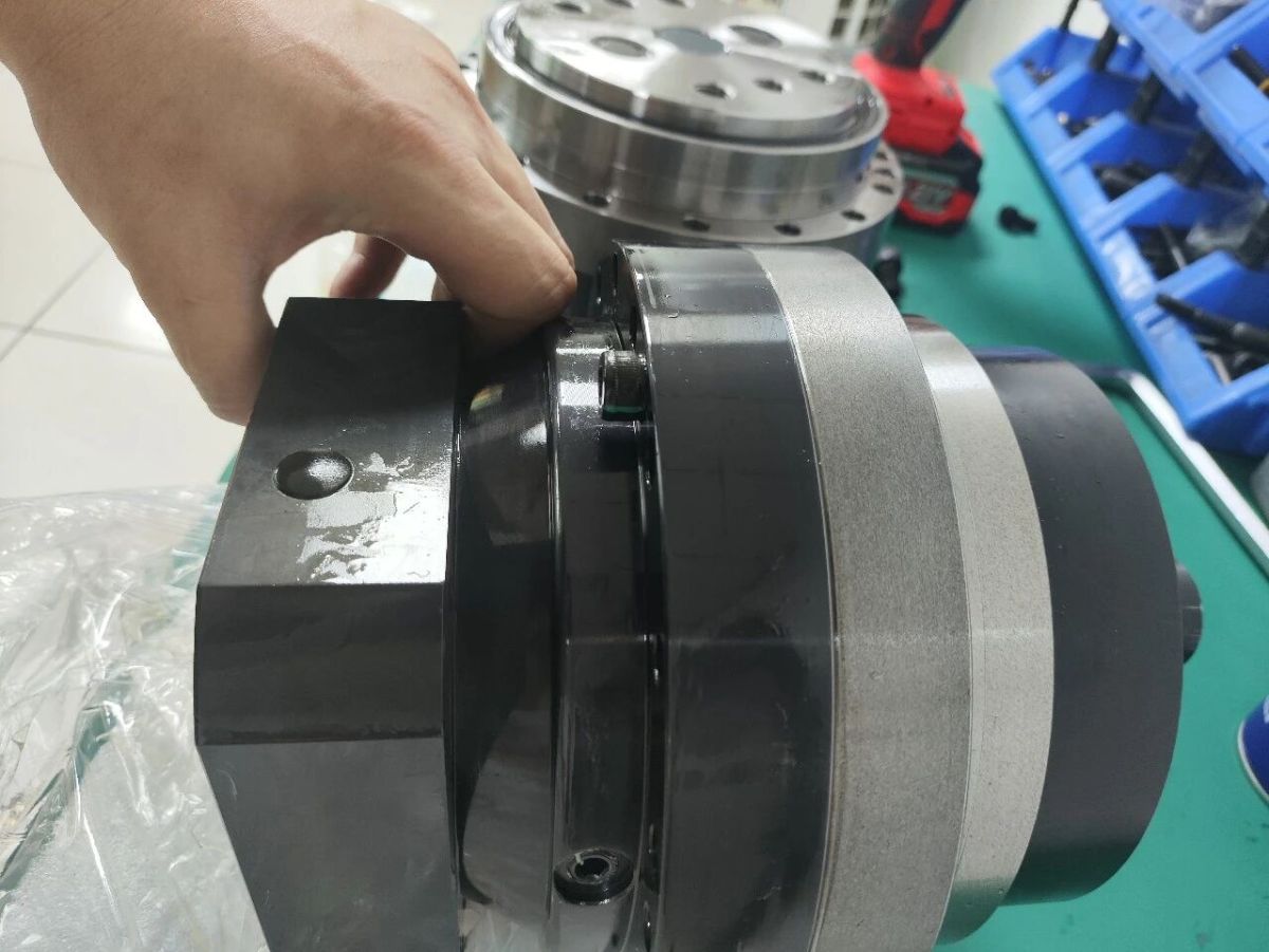
A flange primarily provides connection, positioning, load support, load transmission, and installation accuracy. It is far more than a mechanical component used simply for mounting. It directly affects the assembly accuracy and operational stability of the interface between a reducer and a motor, robot joint, or other equipment.
To understand the function of a reducer flange, we must first examine the fundamental engineering principles behind flanges as mechanical components, then explore the specific functions they perform in precision transmission systems.
Hello everyone, I'm Theodore Li, Technical Director at HONPINE.
What Is a Flange on a Reducer?
In engineering, a flange connection is not simply a single component but an integrated system. The flange provides the bolt holes and sealing surface, the bolts generate the clamping force, and the gasket deforms under compression to fill microscopic gaps on the sealing surfaces.
Sealing does not depend solely on the flange material acting as a physical barrier. Instead, it relies on the force-closed system formed by the bolts, gasket, and flange.
If the preload is insufficient, the gasket cannot compress adequately. If the preload is excessive or unevenly distributed, the flange may undergo plastic deformation or warping. Therefore, the performance of a flanged joint depends on the entire assembly rather than on the flange alone.
One of the key advantages of a flange is its removability. Unlike welded joints or interference fits, a flange connection can be repeatedly assembled and disassembled without destroying the connection interface. This makes flanges one of the most widely used connection methods in piping systems, pressure vessels, and rotating machinery.
Flanges are also highly standardized compared with many other mechanical components. Steel pipe flanges, for example, use two major nominal pressure designation systems: PN and Class. Sealing faces include flat-face, raised-face, male-and-female, tongue-and-groove, and ring-type joint configurations.
Each classification corresponds to specific dimensional requirements, materials, and pressure-temperature ratings. Details such as the bolt circle diameter, sealing surface roughness, and bolt engagement depth cannot be determined simply by visual estimation during installation.
Why Do Flanges Carry Greater Engineering Responsibility in Reducers Than in Ordinary Piping Systems?
A reducer contains a precision motion-transmission system composed of gears and bearings. Flanges may be located at the input interface connecting the reducer to a motor, the output interface connecting it to the driven machinery, or the housing split interface.
Hengchi Transmission has summarized the functions of reducer flanges as connection, sealing, and load support. This is a reasonable starting point, but in precision transmission systems, each function has an additional consequence: accuracy.
In a piping system, flange misalignment primarily affects sealing performance. In a reducer, misalignment at the flange interface can also affect gear meshing conditions and bearing load distribution.
1 Connection: The Key Is Not Simply Joining Components, but Maintaining Alignment
The input flange secures the motor housing to the input-side housing of the reducer, while the output flange secures the reducer housing to the equipment frame.
The flange itself does not directly connect two rotating shafts. Torque is transmitted between shafts through components such as couplings, splines, or hollow shafts. However, the flange's locating pilot or shoulder determines whether the connected shafts can maintain sufficiently accurate coaxial alignment.
Flender's gearbox documentation emphasizes that the service life of shafts, bearings, and couplings depends largely on shaft alignment accuracy. Minimizing alignment deviations is therefore essential. Excessive angular or axial misalignment between connected shafts can lead to premature wear and component damage.
The locating shoulder on a reducer flange helps limit these deviations to acceptable levels.
For example, SEW-EURODRIVE installation specifications reference DIN 42948 for flange locating shoulder tolerances. For locating shoulder diameters (b_1 leq 230) mm, the tolerance is specified as ISO j6; for (b_1 > 230) mm, ISO h6 is used.
These tolerance grades are not merely optional recommendations. They are important for ensuring that the locating interface functions effectively at the scale of tens of micrometers.
The quality of contact between mounting surfaces is another frequently overlooked factor.
If the reducer mounting flange does not sit properly against the equipment mounting surface, or if bolts are tightened in the wrong sequence or with uneven torque, the housing may undergo small but potentially significant elastic deformation during assembly.
Such deformation may be difficult to detect when the equipment is stationary, yet it can alter bearing bore alignment and the parallelism of gear shaft axes.
Engineering analyses indicate that installation-induced deformation can sometimes have a greater negative effect on gear meshing accuracy than the reducer's original manufacturing tolerances.
In other words, even a precisely manufactured flange can lose much of its accuracy advantage if the installation process is not properly controlled.
2 Load Support: The Key Is Not Simply Withstanding Forces, but Directing the Load Path
In a flange-mounted reducer, the output shaft may extend outward without direct support near the driven component. Radial forces generated by pulleys, sprockets, or gears can create an overhung bending moment on the output shaft and its bearings.
SEW technical documentation explains that such overhung loads place additional stress on shafts and bearings. If the permissible limits are exceeded, premature bearing failure may occur. In severe cases, the shaft may even fail due to bending fatigue.
The flange's role is not to absorb the bending moment on behalf of the bearings. Rather, it rigidly secures the reducer housing to the equipment frame and helps transfer reaction torque and external loads into the supporting structure while keeping housing deformation under control.
This function requires sufficient stiffness, not merely adequate strength.
Flender documentation highlights that an insufficiently rigid foundation can cause radial and axial displacement of gearbox components during operation, even when such displacement cannot be detected while the gearbox is stationary.
The Siemens SIMOGEAR operating instructions also establish an important boundary: additional external forces caused by user-installed components must not be imposed on the reducer, and the reducer or geared motor must not be used as a load-bearing support for other components.
The engineering principle behind this restriction is straightforward. The reducer flange and housing are designed to withstand transmission reaction torque and the loads associated with the intended installation. They are not automatically designed to support the weight or inertial loads of additional assemblies.
Using a reducer as a structural support introduces forces and bending moments into a load path that may not have been designed or verified for them. The resulting housing deformation can compromise internal gear meshing conditions.
It is also important to distinguish between structural stress in the flange itself and contact stress at the flange interface. These are two different physical quantities.
In finite element analysis, structural stress near a flange transition radius may reach several hundred megapascals. By contrast, under standard preload conditions, gasket contact stress is often in the range of tens of megapascals.
For example, GORE gasket installation guidance cites a gasket stress design reference of 17 MPa (2,500 psi), with a recommended minimum value (Q_{min} L_{0.1}) of 21 MPa (3,045 psi).
Confusing peak structural stress with contact pressure can lead to order-of-magnitude errors when interpreting the actual contact stress at a preloaded flange interface. These quantities must be clearly distinguished when using engineering data.
3 Sealing: The Key Is Not Simply Preventing Leakage, but Maintaining the Integrity of the Lubrication Boundary
Reducers contain lubricating oil that must remain within the housing under normal operating conditions.
Sealing at the input and output interfaces must achieve two objectives simultaneously: preventing lubricating oil from leaking outward and preventing external contaminants, moisture, and corrosive substances from entering the housing.
Lubricant leakage is more than a maintenance issue. As the oil level decreases, the gears and bearings may receive insufficient lubrication, accelerating wear.
External contamination can be equally damaging. Dust and other particles entering the gear mesh or bearing raceways effectively introduce abrasive material into a precision transmission system.
For this reason, sealing solutions for reducer flanges often involve more than a simple gasket.
SEW installation instructions for certain adapters and flange interfaces specify the use of anaerobic flange sealants such as Loctite 574 or Loctite 5188. The instructions also specify that the sealant should be applied to only one mating surface and distributed continuously without gaps.
Loctite 574 is designed for close-fitting, rigid metal flange connections. It can fill gaps of up to 0.25 mm and cures in the absence of air, providing resistance to low-pressure exposure after assembly.
SEW also specifies tightening torques for certain flange bolts:
M6: 12 Nm
M8: 28 Nm
M10: 56 Nm
M12: 96 Nm
M16: 235 Nm
The specified torque tolerance is ±15%.
These values illustrate that flange sealing is a system-level result determined by several factors, including surface cleanliness, continuous sealant application, and uniform bolt preload.
A deviation in any one of these factors can cause the sealing interface to fail under operating temperatures and vibration.
4 An Often-Overlooked Factor: How Installation Orientation Changes the Flange's Mechanical Role
Foot mounting and flange mounting are not mechanically equivalent.
With foot mounting, the reducer's weight is supported by the base. Depending on the application, the output shaft may primarily transmit torque while experiencing relatively limited radial loading.
With flange mounting, the reducer may be suspended from its mounting interface, leaving the output shaft exposed to overhung loads. The bearings must then accommodate the resulting forces and bending moments within their rated limits.
Consequently, the permissible radial load and bending moment for the output shaft and bearings may differ significantly depending on the installation arrangement.
The flange therefore does more than provide a mounting interface. The selected mounting configuration determines how loads enter the reducer and how they are transmitted through its housing and bearing system.
This, in turn, affects the inputs used to evaluate bearing service life.
Conclusion
The engineering significance of a reducer flange comes from its role at three critical interfaces: the alignment interface, the load-transmission interface, and the sealing interface.
At the alignment interface, locating shoulder tolerances such as those specified under DIN 42948 help preserve the geometric conditions required for accurate gear meshing.
At the load-transmission interface, structural stiffness and bolt preload help transfer reaction torque and external loads into the supporting frame. At the same time, restrictions such as those in the Siemens operating instructions define the limits of acceptable external loading.
At the sealing interface, anaerobic flange sealants fill microscopic gaps and help maintain the boundary between internal lubricant and the external environment.
When any of these interfaces deteriorates—whether through locating shoulder wear, poor mounting surface contact, bolt preload loss, or discontinuous sealant application—the resulting failure rarely begins with the flange itself breaking.
Instead, the consequences may propagate through the transmission system, appearing as gear pitting, bearing spalling, or gradual positioning accuracy drift.
Understanding this relationship reveals a recurring principle in mechanical engineering: fundamental connection components do not always determine the maximum performance of a system, but they can quietly determine its actual performance limits.
For precision transmission systems such as harmonic reducers and RV reducers, a flange should therefore be evaluated not simply as a mounting component, but as an integral part of the system's alignment, structural integrity, and long-term operational reliability.
Read More
Learn more about the story of HONPINE and industry trends related to precision transmission.
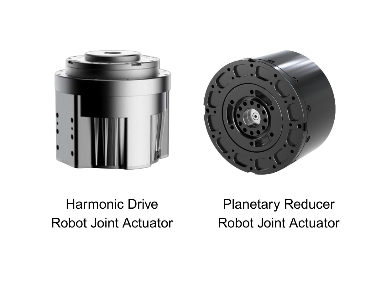
 What is robot joint actuator?How to Choose the Best Robot Rotary Joint Actuator?In core robot joint transmission solutions, planetary and harmonic rotary actuators each have their own strengths. Choosing the right type based on application requirements is essential to achieve the optimal balance between performance and cost.
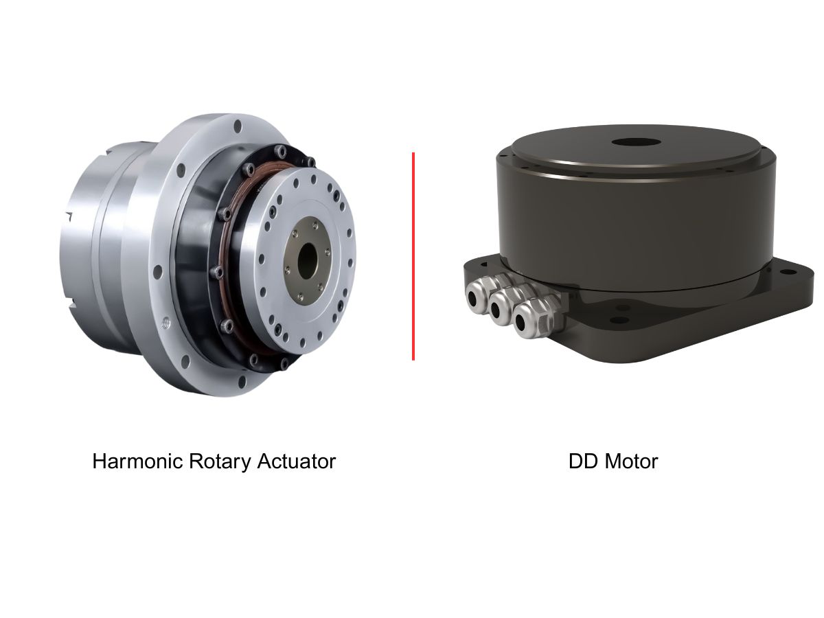
 DD Motors VS Harmonic Rotary ActuatorsThis article provides an in-depth comparison between Direct Drive (DD) motors and harmonic rotary actuators, covering their transmission principles, advantages and disadvantages, and typical application fields.
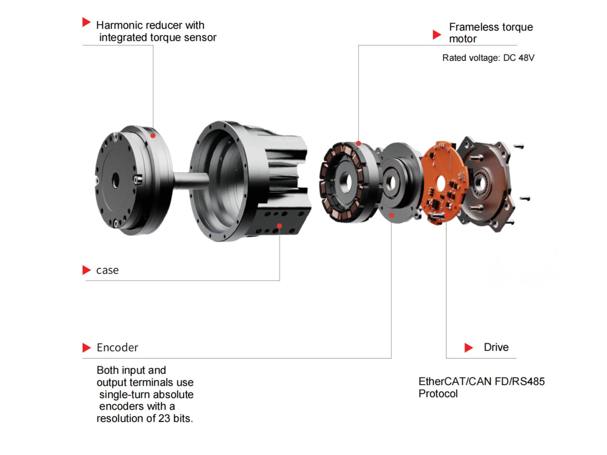
 OMG Ultra Compact Harmonic Drive Joint Module with Built-in Torque SensorHONPINE TCHL series harmonic drive joint module is a game-changing product that achieves disruptive improvements in multiple aspects such as lightweight design, integration level, and connection convenience. This article will analyze its revolutionary enhancements with you.
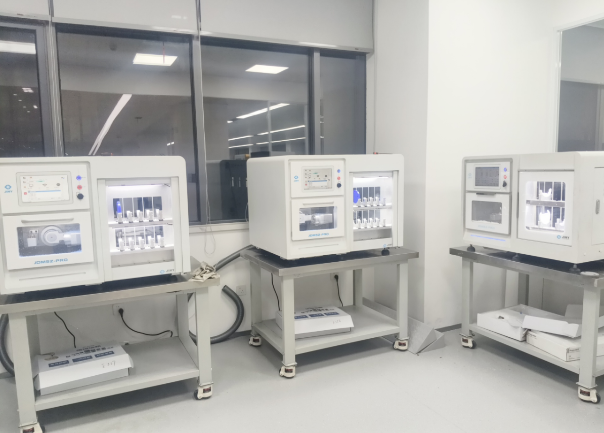
 The Role of Harmonic Drive Gears in Achieving 5–10 μm Accuracy in Dental Milling MachinesA dental milling machine is a CNC machining system used to directly process digital dental models into restorations such as crowns, bridges, veneers, inlays, and implant abutments. Dental milling machines require far higher operational accuracy and motion stability than ordinary equipment. This article explains how harmonic drive gear help dental milling machines achieve stable, continuous, and controllable operation.
 Why Are Harmonic Rotary Actuators Perfect for Medical Equipment?Harmonic rotary actuators (typically integrated systems consisting of a harmonic drive reducer, frameless torque motor, encoder, and optional brake) are regarded as key components in medical equipment. The core reason is that they simultaneously meet the most stringent medical requirements for precision, compact size, safety, and controllability. The following explanation is structured from three perspectives: technical characteristics, application scenarios, and medical value.
 High-Precision RV Reducers Perfectly Matched for Walking RobotsThe walking axis of a robot is a core component for power transmission and support. RV reducers provide extremely high rigidity, precision, and torque while maintaining a compact size and exceptional reliability, making them an ideal match for the demanding requirements of walking robot joints in terms of load capacity, impact resistance, and precision.
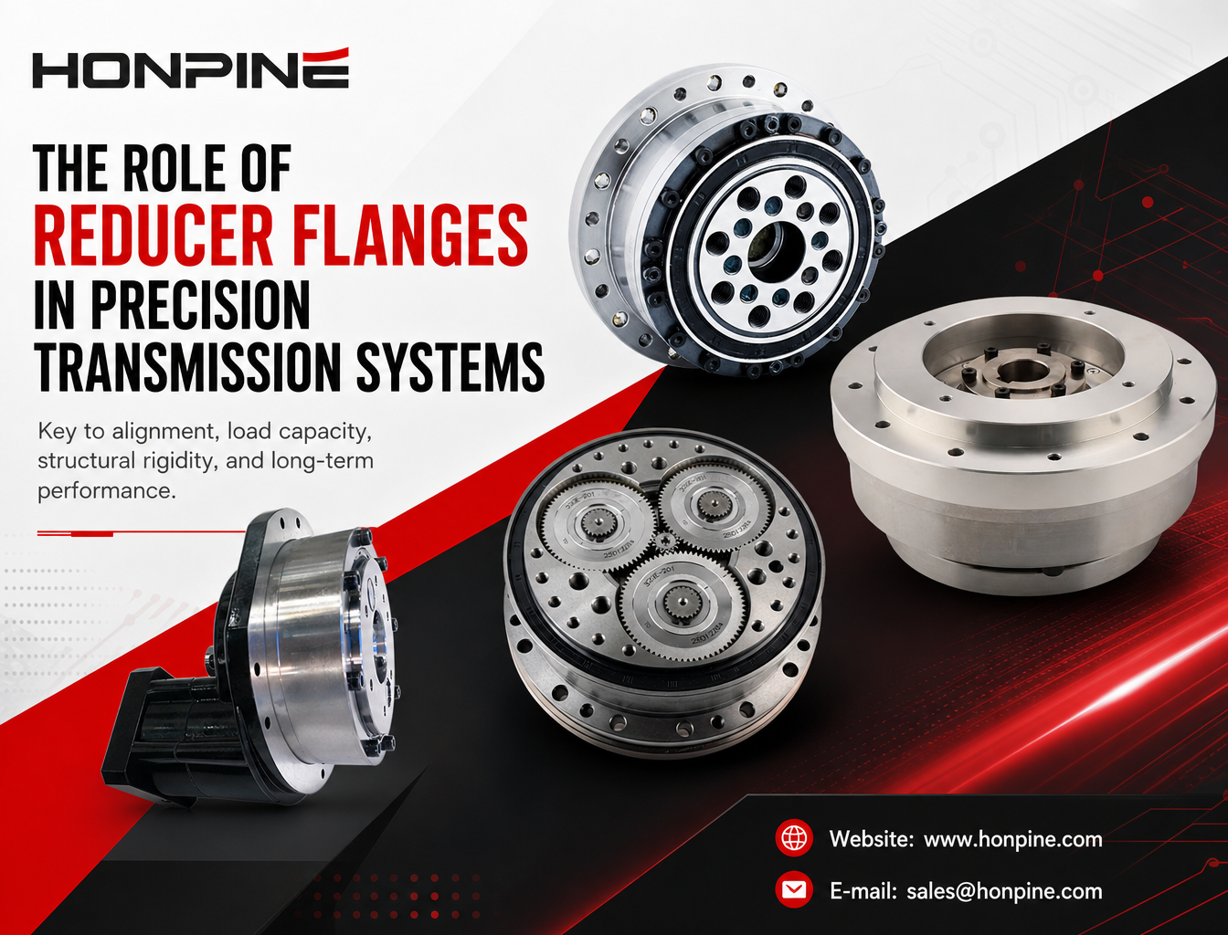
 Why Are Flanges on Harmonic and RV Reducers More Than Just Mechanical Mounting Components?A flange on a harmonic reducer or RV reducer is more than a mounting interface. It plays a critical role in alignment accuracy, load transmission, structural stiffness, and sealing performance. Even minor errors in flange design or installation can affect gear meshing, bearing life, and the overall reliability of a precision motion system. In this article, Theodore Li, Technical Director at HONPINE, explains the key engineering functions of reducer flanges and why they deserve careful consideration when designing and installing precision transmission systems.
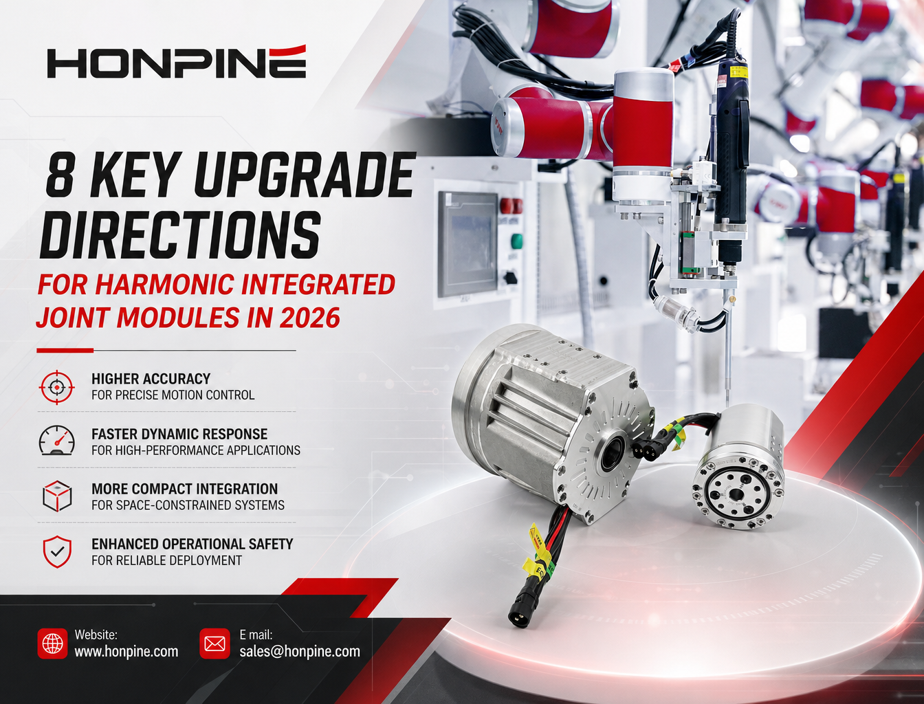
 How Should Manufacturers Upgrade Harmonic Joint Modules for Robotic Arms and Embodied AI in 2026?For engineers planning a robotic system upgrade, the right joint module depends on more than a single specification. EtherCAT synchronization, output-side position feedback, real-time torque measurement, continuous torque capability, and integrated safety functions must work together to meet the demands of the application. By evaluating these factors as a complete electromechanical system, manufacturers can make more informed decisions about joint module selection, integration, and long-term performance.
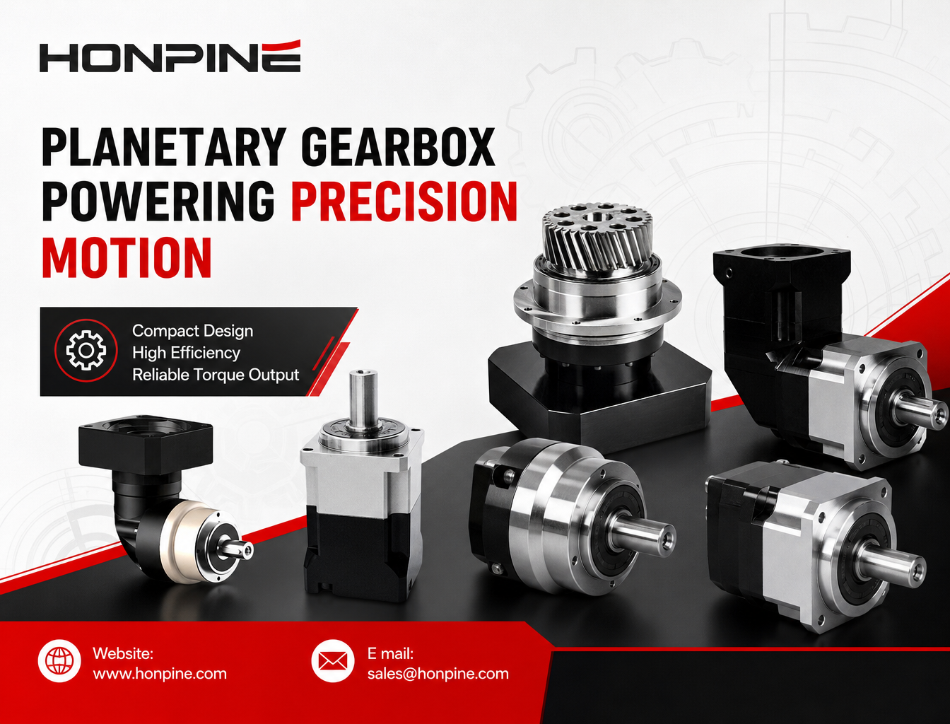
 How Do Planetary Gearboxes Reduce Speed and Increase Torque in High-Precision Automation Equipment?How does a planetary gearbox reduce speed while increasing torque in high-precision automation equipment? By combining a sun gear, multiple planet gears, and an internal ring gear, a planetary gearbox delivers compact, efficient power transmission for applications that require controlled motion and reliable torque output. From industrial robots and CNC machinery to automated assembly systems, selecting the right gearbox involves more than choosing a reduction ratio. This guide explains how planetary gearboxes work, their key advantages, common applications, and practical selection considerations to help engineers identify a suitable transmission solution.
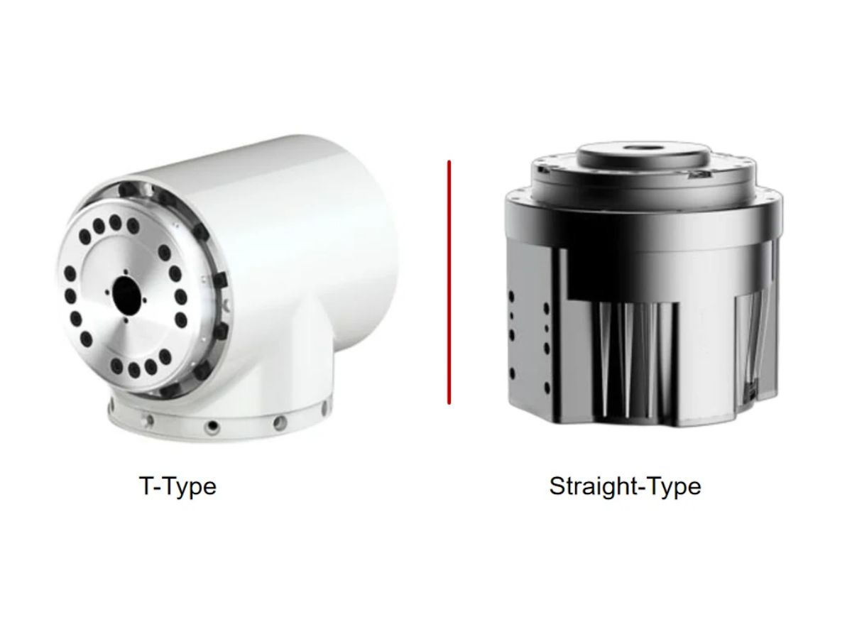
 Should You Choose a T-Type or Straight-Type Harmonic Joint Module for a Collaborative Robot?Choosing the right harmonic joint module is essential when designing a compact, high-performance collaborative robot. Should you use a TCHL straight-type or an HTS T-type harmonic joint module? Although both configurations can support precise robotic motion, their different output flange geometries affect installation space, link connections, cable routing, and mechanical integration. In this guide, Theodore Li, Technical Director at HONPINE, explains the key differences between the two designs, their advantages and limitations, and how to select the most suitable configuration for your collaborative robotic arm.
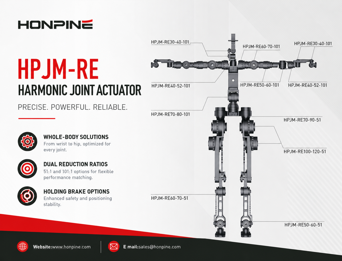
 The Complete Harmonic Joint Actuator Solution for Humanoid Robots: HPJM Series Selection GuideA complete guide to selecting harmonic joint actuators for humanoid robots. Explore HONPINE HPJM models for wrist, elbow, shoulder, waist, hip, knee, and ankle joints, with practical considerations for torque capacity, reduction ratios, dynamic response, and holding brake configurations.
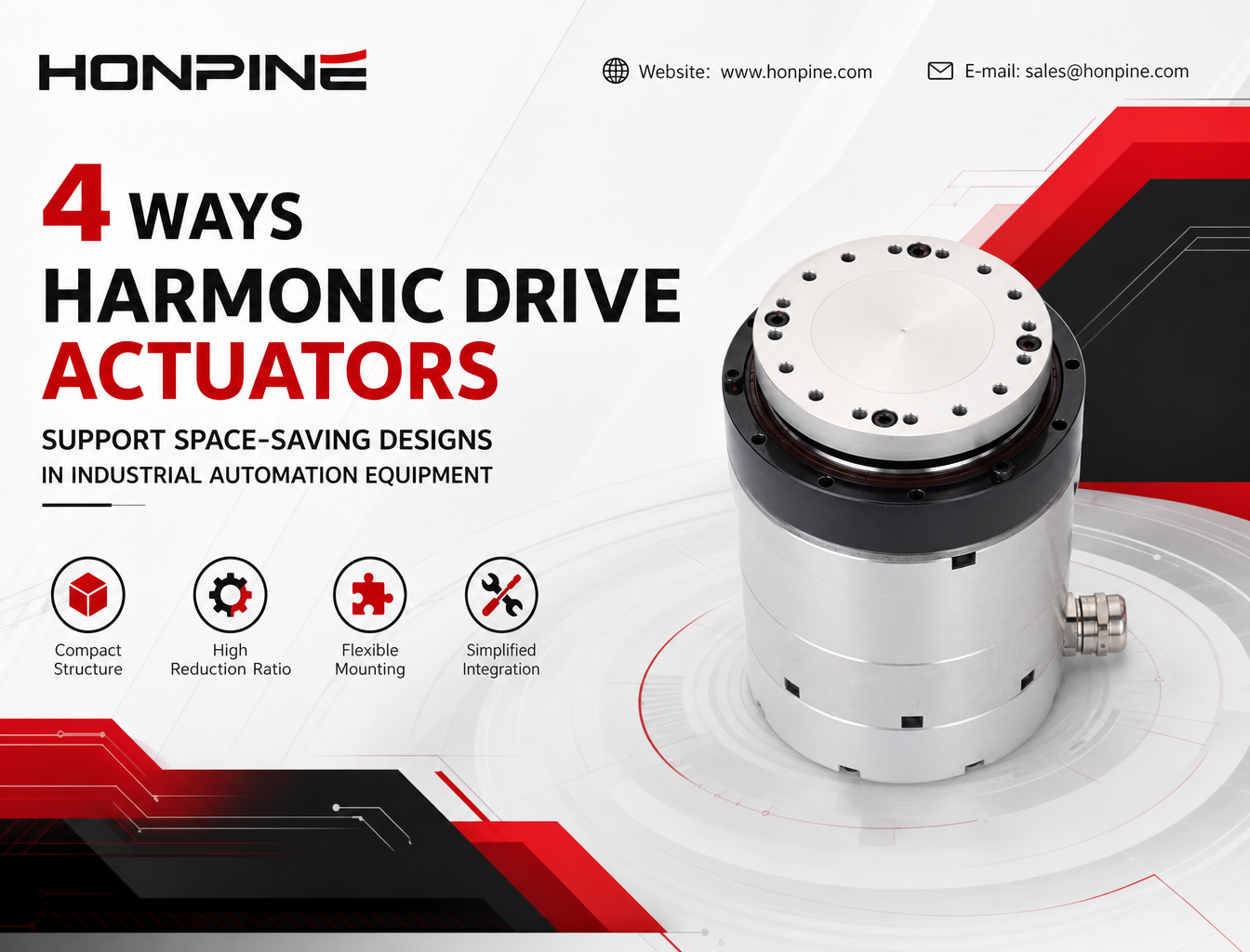
 Why Are Harmonic Drive Actuators Ideal for Space-Constrained Industrial Automation Equipment?In modern industrial automation, limited installation space often makes mechanical design more challenging. Harmonic drive actuators offer a compact motion-control solution by integrating key drive components into a single unit. Their high reduction ratios, streamlined mechanical structures, and flexible mounting options can help equipment manufacturers reduce space requirements, simplify assembly, and optimize internal layouts. This article explores four ways integrated harmonic drive actuators support space-saving designs in industrial automation equipment.
Double Click
We provide harmonic drive reducer,planetary reducer,robot joint motor,robot rotary actuators,RV gear reducer,robot end effector,dexterous robot hand
 What is robot joint actuator?How to Choose the Best Robot Rotary Joint Actuator?In core robot joint transmission solutions, planetary and harmonic rotary actuators each have their own strengths. Choosing the right type based on application requirements is essential to achieve the optimal balance between performance and cost.
 DD Motors VS Harmonic Rotary ActuatorsThis article provides an in-depth comparison between Direct Drive (DD) motors and harmonic rotary actuators, covering their transmission principles, advantages and disadvantages, and typical application fields.
 OMG Ultra Compact Harmonic Drive Joint Module with Built-in Torque SensorHONPINE TCHL series harmonic drive joint module is a game-changing product that achieves disruptive improvements in multiple aspects such as lightweight design, integration level, and connection convenience. This article will analyze its revolutionary enhancements with you.
 Why Are Flanges on Harmonic and RV Reducers More Than Just Mechanical Mounting Components?A flange on a harmonic reducer or RV reducer is more than a mounting interface. It plays a critical role in alignment accuracy, load transmission, structural stiffness, and sealing performance. Even minor errors in flange design or installation can affect gear meshing, bearing life, and the overall reliability of a precision motion system. In this article, Theodore Li, Technical Director at HONPINE, explains the key engineering functions of reducer flanges and why they deserve careful consideration when designing and installing precision transmission systems.
 How Should Manufacturers Upgrade Harmonic Joint Modules for Robotic Arms and Embodied AI in 2026?For engineers planning a robotic system upgrade, the right joint module depends on more than a single specification. EtherCAT synchronization, output-side position feedback, real-time torque measurement, continuous torque capability, and integrated safety functions must work together to meet the demands of the application. By evaluating these factors as a complete electromechanical system, manufacturers can make more informed decisions about joint module selection, integration, and long-term performance.
 How Do Planetary Gearboxes Reduce Speed and Increase Torque in High-Precision Automation Equipment?How does a planetary gearbox reduce speed while increasing torque in high-precision automation equipment? By combining a sun gear, multiple planet gears, and an internal ring gear, a planetary gearbox delivers compact, efficient power transmission for applications that require controlled motion and reliable torque output. From industrial robots and CNC machinery to automated assembly systems, selecting the right gearbox involves more than choosing a reduction ratio. This guide explains how planetary gearboxes work, their key advantages, common applications, and practical selection considerations to help engineers identify a suitable transmission solution.
 Should You Choose a T-Type or Straight-Type Harmonic Joint Module for a Collaborative Robot?Choosing the right harmonic joint module is essential when designing a compact, high-performance collaborative robot. Should you use a TCHL straight-type or an HTS T-type harmonic joint module? Although both configurations can support precise robotic motion, their different output flange geometries affect installation space, link connections, cable routing, and mechanical integration. In this guide, Theodore Li, Technical Director at HONPINE, explains the key differences between the two designs, their advantages and limitations, and how to select the most suitable configuration for your collaborative robotic arm.
 The Complete Harmonic Joint Actuator Solution for Humanoid Robots: HPJM Series Selection GuideA complete guide to selecting harmonic joint actuators for humanoid robots. Explore HONPINE HPJM models for wrist, elbow, shoulder, waist, hip, knee, and ankle joints, with practical considerations for torque capacity, reduction ratios, dynamic response, and holding brake configurations.
 Why Are Harmonic Drive Actuators Ideal for Space-Constrained Industrial Automation Equipment?In modern industrial automation, limited installation space often makes mechanical design more challenging. Harmonic drive actuators offer a compact motion-control solution by integrating key drive components into a single unit. Their high reduction ratios, streamlined mechanical structures, and flexible mounting options can help equipment manufacturers reduce space requirements, simplify assembly, and optimize internal layouts. This article explores four ways integrated harmonic drive actuators support space-saving designs in industrial automation equipment.
 Single-Turn vs. Multi-Turn Absolute Encoders for Robot Joint Modules: How to Choose?This guide compares single-turn and multi-turn absolute encoders for robot joint modules, explaining how they differ in position feedback, power-off position retention, and maintenance requirements. Learn how to select the right encoder configuration for humanoid robots, collaborative robotic arms, and exoskeletons using the HONPINE HPJM Harmonic Joint Actuator PRO Series as an example.
 STO vs. Holding Brake in Robot Joint Modules: What Is the Difference for Robot Safe Control?STO (Safe Torque Off) and holding brakes play different roles in robot joint safety. While STO prevents a motor from generating driving torque, a holding brake mechanically resists joint movement and helps retain loads when the motor is disabled. Understanding the difference is essential when selecting a robot joint module for humanoid robots, collaborative robots, and industrial automation. In this article, Theodore Li, Technical Director at HONPINE, explains how these functions work, their limitations, and when both should be considered in a harmonic integrated joint actuator such as the HONPINE HAG series.
 AGV Robot Steering Drive Wheel: A Comprehensive Guide to Components, Applications, and SelectionAn AGV steering drive wheel integrates traction and active steering to support flexible movement in industrial mobile robots. This guide explains its main components, working principles, industrial applications, and key selection factors, including load capacity, traction torque, steering torque, wheel diameter, speed, and control interfaces. Discover how to choose a suitable steering drive module for AGVs, AMRs, autonomous forklifts, and heavy-duty material handling systems.