







How to Select a Harmonic Reducer: 9 Key Factors You Need to Know
Hello everyone, I’m Theodore Li, Technical Director at HONPINE.
In previous articles, I have discussed different aspects of harmonic reducer selection, including how to calculate the reduction ratio. However, selecting the right harmonic reducer involves much more than choosing a ratio or comparing torque values.
A harmonic reducer mainly consists of three core components: the wave generator, flexspline, and circular spline. A reliable selection process starts with matching the reducer to the application and load dynamics, followed by checking torque capacity, service life, installation constraints, positioning accuracy, and operating conditions.
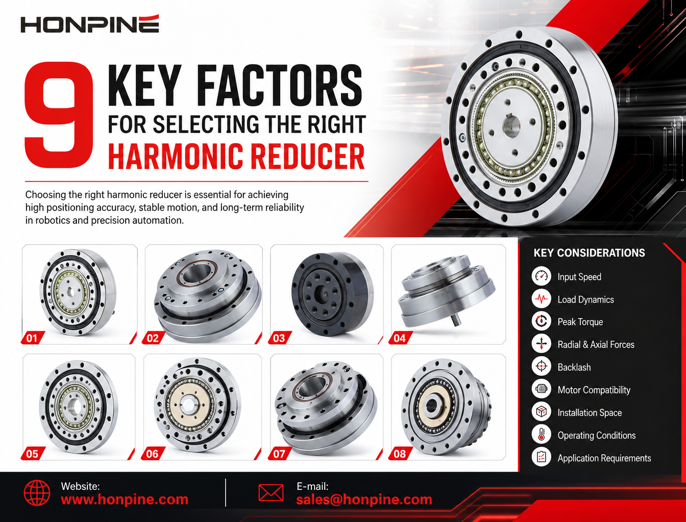
When selecting a harmonic reducer, engineers should not focus on torque alone. The right selection requires evaluating the application scenario, reduction ratio, input speed, torque requirements, external loads, positioning accuracy, motor interface, installation space, and operating environment.
This article explains the 9 key factors you need to consider when selecting a harmonic reducer and provides a practical selection process for robots, servo rotary tables, robot joints, and automated equipment.
Before getting started, remember one important principle:
A harmonic reducer should not be selected based on rated torque alone. Shock loads, inertia matching, and overturning moments are often the real causes of failure.
In many cases, a reducer does not fail because its continuous torque rating has been exceeded. Instead, failure is caused by excessive shock loads, overturning moments, or poor inertia matching.
1. Define the Application Scenario
The application is the starting point for harmonic reducer selection. It directly affects the required safety factor, accuracy level, lubrication, environmental protection, and service life.
Humanoid Robot Joints and Collaborative Robots
These applications typically involve frequent starts and stops, reciprocating motion, low-speed operation, and high dynamic performance. They usually require low backlash, lightweight construction, and integrated support bearings.
A relatively high safety factor, typically between 1.5 and 2.0, is often recommended. Key considerations include fatigue life, micro-vibration, and long-term backlash stability.
Semiconductor Wafer Handling and Inspection Rotary Tables
These applications require high positioning accuracy, low particle generation, clean operating environments, and smooth low-speed motion.
Priority should be given to low backlash, low torque fluctuation, and vacuum-compatible or cleanroom-compatible lubrication.
Servo Indexing Tables and Fixture Rotation Systems
These applications usually operate intermittently and may experience shock loads. Peak torque and shock torque should therefore be carefully verified.
Gimbals and Electro-Optical Payloads
These systems typically operate at low speeds and are strongly affected by load inertia. Lost motion and friction torque are particularly important selection factors.
2. Select the Appropriate Reduction Ratio
Common harmonic reducer ratios include 50:1, 80:1, 100:1, 120:1, and 160:1, while some models are also available in ratios such as 30:1 or 200:1.
Unlike some other gear systems, the reduction ratio of a harmonic reducer cannot be selected arbitrarily because it is constrained by the tooth profile and structural design.
In a conventional harmonic drive structure, where the wave generator is the input, the reduction ratio can be expressed as:
Reduction Ratio = Number of Flexspline Teeth ÷ (Number of Circular Spline Teeth − Number of Flexspline Teeth)
Start with Output Speed and Motor Speed
The target output speed and the rated speed of the motor should be used to determine an initial reduction ratio.
Consider Inertia Matching
The load inertia reflected to the motor shaft decreases as the reduction ratio increases. A higher reduction ratio can therefore make inertia matching easier for the motor.
For the same output torque, a higher reduction ratio also reduces the required input torque. In addition, the angular error reflected to the motor side is reduced by the reduction ratio.
However, a higher reduction ratio also has disadvantages. It can reduce the maximum available output speed and may affect the dynamic response of the system.
Check the Maximum Input Speed
Harmonic reducers have a maximum allowable input speed due to limitations associated with the wave generator and flexible bearing.
Some higher-ratio models may have lower allowable maximum input speeds. Therefore, the motor speed should not be considered independently.
Do not simply choose the largest possible reduction ratio. If the application requires a high output speed, the motor may exceed the maximum allowable input speed of the harmonic reducer.
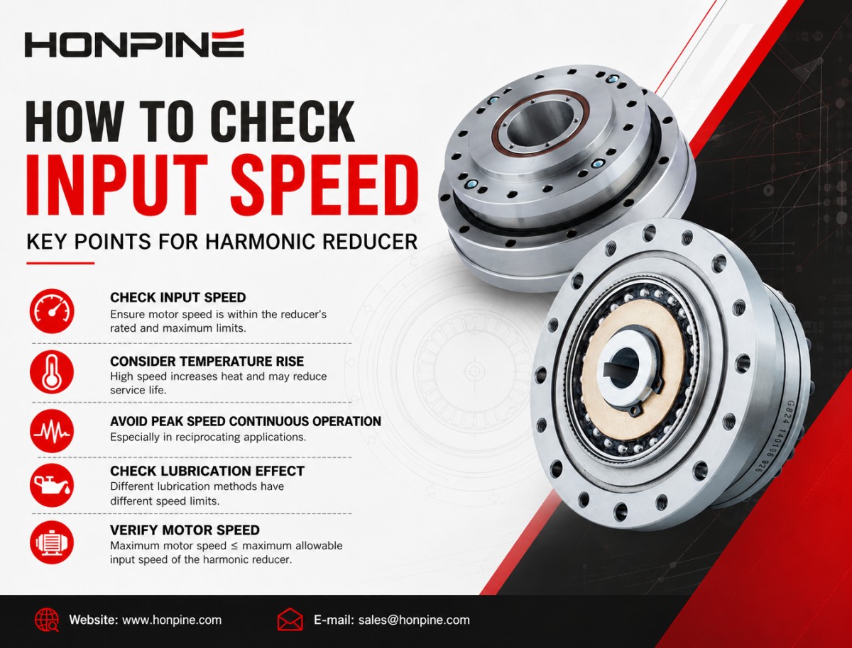
3. Check the Input Speed
Input speed refers to the rotational speed of the wave generator, or the motor-side speed. It is not the output speed of the reducer.
Product catalogs usually specify two important values:
Rated Continuous Input Speed: The recommended speed for long-term continuous operation while maintaining the specified service life and temperature limits.
Maximum Instantaneous Input Speed: The maximum speed allowed for short periods. It should not be used for continuous operation.
Consider Temperature Rise
Continuous operation at high speed can accelerate the aging of the flexible bearing and lubricant. Excessive temperature rise can significantly reduce the service life of the harmonic reducer.
Do Not Use Peak Speed for Continuous Operation
This is particularly important in reciprocating applications, where repeated acceleration and deceleration can generate significant heat.
Check the Effect of Lubrication
Different lubrication methods have different speed limits. Grease lubrication generally has a lower speed limit than oil lubrication, while specialized lubricants for cleanroom or vacuum environments may have even stricter limitations.
Verify Motor Speed Against the Reducer Limit
Maximum motor speed ≤ maximum allowable input speed of the harmonic reducer.
4. Understand Torque Requirements
Continuous torque, peak torque, and shock torque are fundamentally different parameters and should never be confused. This is one of the most common mistakes in harmonic reducer selection.
Continuous Output Torque (Tc)
Continuous output torque is the torque that the reducer can continuously transmit under specified conditions, such as rated input speed and standard ambient temperature, while meeting its rated service life requirements.
It is mainly used to verify steady-state loads, including continuous rotation and sustained load torque.
The actual steady-state operating torque should be lower than the continuous output torque, with an appropriate safety margin.
It is important to note that the catalog value for Tc is usually specified under standard test conditions. High temperatures, reciprocating motion, and cleanroom environments may require torque derating.
A typical derating factor may range from 0.7 to 0.9, depending on the operating conditions.
Peak Torque (Tp)
Peak torque is the maximum output torque allowed for a short period, usually during acceleration or deceleration.
The allowable duration may vary by manufacturer and product series. Peak torque should be used to evaluate dynamic operating conditions rather than continuous operation.
Shock Torque
Shock torque refers to a sudden, short-duration torque generated by events such as emergency stops, collisions, or rapid load changes.
A harmonic reducer should not be selected based only on its continuous torque rating. In high-dynamic applications, the maximum shock load must also be evaluated to avoid damage to the flexspline, gear teeth, or internal bearings.
5. Check Radial Load, Axial Load, and Overturning Moment
This is one of the most important considerations in harmonic reducer selection.
Most standard harmonic reducers are not designed to withstand large radial loads, axial loads, or overturning moments directly.
The internal flexspline and flexible bearing are primarily designed to transmit torque and should not be treated as the main load-supporting bearing system.
Only harmonic reducers with integrated support bearings, such as cross-roller bearings used in certain actuator or robot joint designs, are typically specified with allowable radial load, axial load, and overturning moment values.
Radial Load (Fr)
A force acting perpendicular to the output shaft axis.
Axial Load (Fa)
A pushing or pulling force acting along the output shaft axis.
Overturning Moment (M)
An overturning moment is generated when the load center of gravity is offset from the output axis.
This is particularly common in robot arms carrying an eccentric end load.
When selecting a harmonic reducer for these applications, the allowable loads and moments must be checked carefully against the manufacturer's specifications.
6. Evaluate Accuracy Requirements
Backlash and lost motion are often confused, but they are not the same. Both should be considered when selecting a harmonic reducer for positioning applications.
What Is Backlash?
Backlash, also known as angular clearance, refers to the amount of output rotation that occurs when the direction of motion is reversed while the input is fixed.
Harmonic reducers are known for their extremely low backlash. Typical specifications may be ≤1 arcmin or ≤0.5 arcmin, while higher-precision models can achieve values below 0.3 arcmin.
However, harmonic reducers are not truly zero-backlash systems.
Their low-backlash performance is achieved through elastic deformation and preload. Over long periods of operation or after overload events, backlash may gradually increase due to fatigue and wear.
What Is Lost Motion?
Lost motion includes not only mechanical backlash but also the angular deformation caused by the elastic flexibility of the transmission components.
When output torque is applied, the flexspline and other elastic components may deform, creating an angular delay between the input and output.
How to Select the Right Accuracy Level?
For general power transmission and constant-speed conveying, standard accuracy is usually sufficient.
For vision alignment, electro-optical rotary tables, and semiconductor positioning, a low lost-motion grade should be prioritized.
An important characteristic of harmonic reducers is that lost motion changes with output torque. Higher torque can produce greater elastic deformation and therefore greater lost motion.
This is an inherent characteristic of harmonic drive systems and differs significantly from conventional planetary gearboxes.
7. Verify the Motor Flange and Shaft Dimensions
The input side of a harmonic reducer connects to the wave generator. A typical wave generator consists of a flexible bearing and an elliptical cam, which must be connected accurately to the motor shaft.
Common Connection Methods
Common connection methods include set screws, key connections, and locking assemblies.
Locking assemblies can provide a backlash-free connection and are often preferred in high-precision applications and robot joints.
Motor Interface Selection Checklist
The following parameters should be verified:
Motor flange mounting hole pattern
Pilot diameter
Compatibility with the harmonic reducer input flange
Motor shaft diameter
Shaft extension length
Keyway dimensions
Motor shaft tolerances
If the motor flange does not match the reducer, an adapter flange may be required.
Avoid Poor Concentricity
Motor shaft tolerances are also important. Excessive tolerance or poor concentricity can cause misalignment of the wave generator, leading to increased vibration, wear, and transmission errors.
Poor concentricity between an adapter flange, motor shaft, and wave generator can cause premature failure of the flexible bearing.
Provide the Motor Drawing to the Manufacturer
A good engineering practice is to provide the motor drawing to the harmonic reducer manufacturer so that the wave generator connection, cam dimensions, and any required adapter components can be properly verified.
8. Consider Installation Space
Installation space is another important factor in harmonic reducer selection. The available outside diameter and axial length can directly limit the range of models that can be used.
Harmonic reducers are typically organized into standardized size series, such as Size 14, 17, 20, 25, and 32.
Check the Outside Diameter
The available outside diameter determines the maximum reducer size that can be installed.
In many robot joint designs, the joint diameter is strictly limited. The available outside diameter should therefore be used first to narrow down the possible reducer series.
Check the Axial Length
Different harmonic reducer designs can have significantly different axial dimensions even when their outside diameters are similar.
Cup-type, hat-type, and hollow-shaft designs offer different space configurations.
Balance Size and Torque Capacity
A smaller reducer may be necessary when installation space is limited, but smaller sizes also have lower torque capacity.
In some cases, the available installation space becomes the limiting factor, requiring the designer to reduce the load or consider an alternative transmission solution.
9. Consider Operating Temperature and Environmental Conditions
Operating temperature and environmental conditions have a direct impact on lubrication performance, service life, and long-term reliability.
Operating Temperature
For conventional grease-lubricated harmonic reducers, the allowable operating temperature range depends on the product and lubricant specification.
At high temperatures, lubricating grease may soften, migrate, or degrade more quickly.
At low temperatures, grease viscosity increases, which can significantly increase starting friction torque.
Special high-temperature or low-temperature lubricants may be required for extreme environments.
General Industrial Environments
Basic dust protection may be sufficient for standard industrial applications.
Cleanroom and Semiconductor Applications
Low-particle-generation lubricants and silicone-free grease may be required.
Vacuum Applications
Special vacuum-compatible lubricants or solid lubrication may be necessary. Low outgassing requirements should also be considered.
Humid or Corrosive Environments
Surface protection, sealing structures, and corrosion resistance should be considered to prevent rust and damage to components such as the flexspline.
Dusty Environments
Additional sealing may be required to prevent particles from entering the gear meshing area and accelerating wear.
Check Lubrication and Maintenance Requirements
Lubrication is one of the most important factors affecting the service life of a harmonic reducer.
During the selection process, it is important to confirm whether the reducer is factory pre-lubricated or requires lubrication by the user. The recommended maintenance interval should also be verified.
In general, harmonic reducers are precision components and are not intended for frequent disassembly and maintenance.
Quick Answer: How to Select a Harmonic Reducer
To select the right harmonic reducer, start by defining the application and load conditions. Then evaluate the reduction ratio, input speed, continuous and peak torque, external loads, accuracy requirements, motor interface, installation space, and operating environment.
The most important point is to evaluate the complete operating condition rather than selecting a harmonic reducer based on rated torque alone.
Final Thoughts
Selecting the right harmonic reducer is not simply a matter of comparing torque ratings.
A reliable selection process should begin with the application and load dynamics, followed by a systematic evaluation of all nine key factors discussed in this article.
For high-performance applications such as robot joints, semiconductor equipment, precision positioning systems, and servo rotary tables, overlooking even one of these factors can affect positioning performance, service life, and overall system reliability.
The best harmonic reducer is not necessarily the one with the highest torque rating or the largest reduction ratio. It is the one that matches the actual operating conditions of your system.

About Author
Theodore Li serves as the Technical Director at HONPINE, overseeing the R&D strategy for replication products, guiding team selection, and managing both pre-sales and after-sales operations.

Read More
Learn more about the story of HONPINE and industry trends related to precision transmission.
 What is robot joint actuator?How to Choose the Best Robot Rotary Joint Actuator?In core robot joint transmission solutions, planetary and harmonic rotary actuators each have their own strengths. Choosing the right type based on application requirements is essential to achieve the optimal balance between performance and cost.
 DD Motors VS Harmonic Rotary ActuatorsThis article provides an in-depth comparison between Direct Drive (DD) motors and harmonic rotary actuators, covering their transmission principles, advantages and disadvantages, and typical application fields.
 OMG Ultra Compact Harmonic Drive Joint Module with Built-in Torque SensorHONPINE TCHL series harmonic drive joint module is a game-changing product that achieves disruptive improvements in multiple aspects such as lightweight design, integration level, and connection convenience. This article will analyze its revolutionary enhancements with you.
 The Role of Harmonic Drive Gears in Achieving 5–10 μm Accuracy in Dental Milling MachinesA dental milling machine is a CNC machining system used to directly process digital dental models into restorations such as crowns, bridges, veneers, inlays, and implant abutments. Dental milling machines require far higher operational accuracy and motion stability than ordinary equipment. This article explains how harmonic drive gear help dental milling machines achieve stable, continuous, and controllable operation.
 Why Are Harmonic Rotary Actuators Perfect for Medical Equipment?Harmonic rotary actuators (typically integrated systems consisting of a harmonic drive reducer, frameless torque motor, encoder, and optional brake) are regarded as key components in medical equipment. The core reason is that they simultaneously meet the most stringent medical requirements for precision, compact size, safety, and controllability. The following explanation is structured from three perspectives: technical characteristics, application scenarios, and medical value.
 High-Precision RV Reducers Perfectly Matched for Walking RobotsThe walking axis of a robot is a core component for power transmission and support. RV reducers provide extremely high rigidity, precision, and torque while maintaining a compact size and exceptional reliability, making them an ideal match for the demanding requirements of walking robot joints in terms of load capacity, impact resistance, and precision.
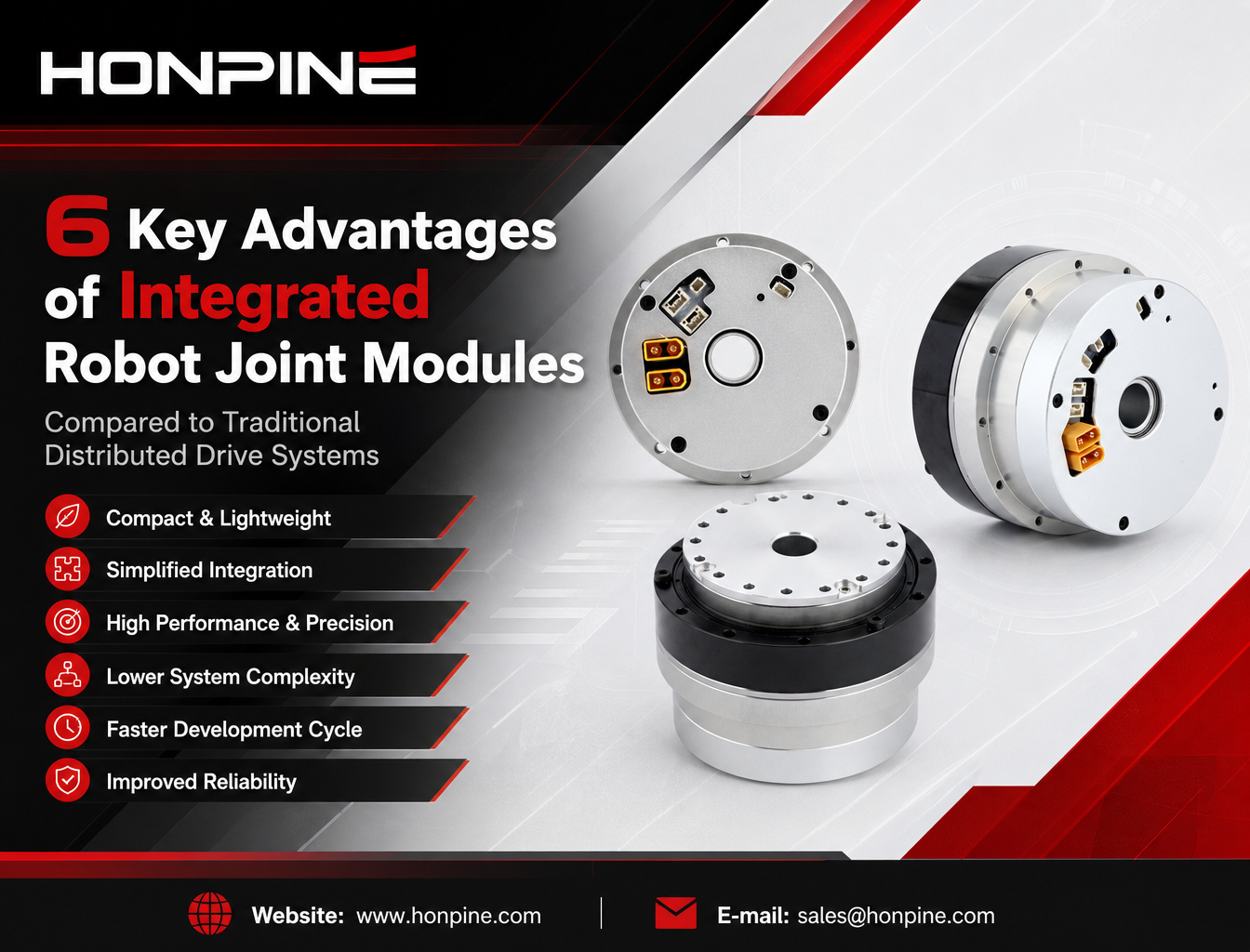
 How to Select a Harmonic Reducer: 9 Key Factors You Need to KnowWhy are more robotics companies choosing integrated robot joint modules instead of traditional distributed drive systems? As humanoid robots, collaborative robots, and rehabilitation exoskeletons continue to evolve, manufacturers are looking for more compact, lightweight, and easier-to-integrate motion solutions. An integrated robot joint module combines essential components such as a frameless torque motor, harmonic reducer, servo drive, encoders, and output bearing into a single assembly. This architecture can reduce mechanical complexity, simplify wiring, improve motion control integration, and shorten robot development cycles. In this article, Theodore Li, Technical Director at HONPINE, explains six key advantages of integrated robot joint modules and compares them with conventional distributed drive configurations.
 Why Are More Companies Choosing Integrated Robot Joint Modules?Integrated robot joint modules combine motors, harmonic reducers, servo drives, encoders, and output bearings into compact units. This article compares integrated and distributed drive architectures, exploring their differences in torque density, mechanical reliability, motion control, development efficiency, and practical robotic applications.
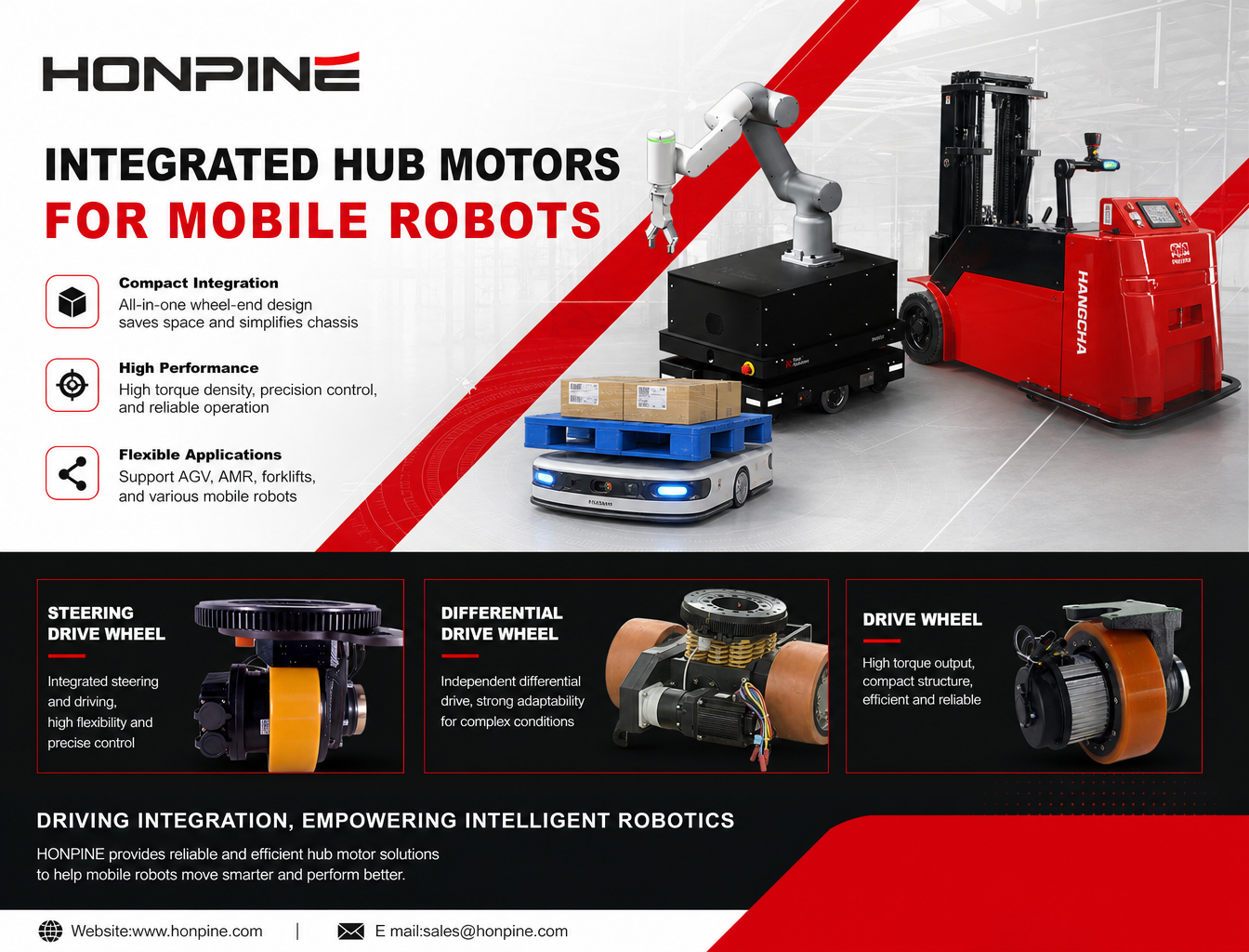
 Why Are More Robots Moving Away from Traditional Drive Systems to Integrated Hub Servo Motors?As mobile robots evolve toward autonomous navigation, flexible operation, and increasingly complex working environments, traditional distributed drive systems are facing new challenges. Separate motors, gearboxes, couplings, and transmission components can increase chassis complexity and limit available installation space. This is why more robot manufacturers are turning to integrated hub servo motors. By combining key drive components within a compact wheel-end unit, hub motors offer new possibilities for improving drive integration, motion control, and chassis design. In this article, we explore the key performance requirements of mobile robots, explain the advantages of integrated hub motors, and examine how HONPINE's Drive Wheels, Steering Drive Wheels, and Differential Drive Wheels support different AGV and AMR applications.
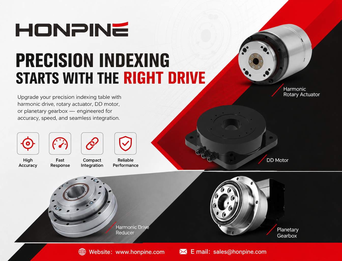
 How Can Precision Reducers, Harmonic Rotary Actuators, and Direct-Drive Motors Upgrade Precision Indexing Tables?How can manufacturers improve the accuracy, dynamic response, and integration of precision indexing tables? As flexible manufacturing continues to evolve, traditional transmission systems may face challenges such as backlash, long settling times, and complex mechanical integration. This article explores how harmonic drive reducers, harmonic rotary actuators, direct-drive (DD) torque motors, and planetary gearboxes provide practical upgrade solutions for different operating conditions. By matching the transmission architecture to positioning accuracy, indexing cycle time, load inertia, and installation constraints, manufacturers can develop more efficient and reliable precision indexing systems.
 Should Robot Manufacturers Develop Their Own Joint Modules or Buy Integrated Joint Modules?Should robot manufacturers develop joint modules in-house or purchase integrated joint modules? This article compares the advantages and disadvantages of both approaches, including development costs, technical ownership, supply chain stability, production efficiency, and long-term scalability. Learn why a hybrid sourcing strategy that combines in-house development with external procurement is becoming a practical option for humanoid robots, robotic arms, and embodied AI systems.
 Why Are Flanges on Harmonic and RV Reducers More Than Just Mechanical Mounting Components?A flange on a harmonic reducer or RV reducer is more than a mounting interface. It plays a critical role in alignment accuracy, load transmission, structural stiffness, and sealing performance. Even minor errors in flange design or installation can affect gear meshing, bearing life, and the overall reliability of a precision motion system. In this article, Theodore Li, Technical Director at HONPINE, explains the key engineering functions of reducer flanges and why they deserve careful consideration when designing and installing precision transmission systems.
Double Click
We provide harmonic drive reducer,planetary reducer,robot joint motor,robot rotary actuators,RV gear reducer,robot end effector,dexterous robot hand
 What is robot joint actuator?How to Choose the Best Robot Rotary Joint Actuator?In core robot joint transmission solutions, planetary and harmonic rotary actuators each have their own strengths. Choosing the right type based on application requirements is essential to achieve the optimal balance between performance and cost.
 DD Motors VS Harmonic Rotary ActuatorsThis article provides an in-depth comparison between Direct Drive (DD) motors and harmonic rotary actuators, covering their transmission principles, advantages and disadvantages, and typical application fields.
 OMG Ultra Compact Harmonic Drive Joint Module with Built-in Torque SensorHONPINE TCHL series harmonic drive joint module is a game-changing product that achieves disruptive improvements in multiple aspects such as lightweight design, integration level, and connection convenience. This article will analyze its revolutionary enhancements with you.
 How to Select a Harmonic Reducer: 9 Key Factors You Need to KnowWhy are more robotics companies choosing integrated robot joint modules instead of traditional distributed drive systems? As humanoid robots, collaborative robots, and rehabilitation exoskeletons continue to evolve, manufacturers are looking for more compact, lightweight, and easier-to-integrate motion solutions. An integrated robot joint module combines essential components such as a frameless torque motor, harmonic reducer, servo drive, encoders, and output bearing into a single assembly. This architecture can reduce mechanical complexity, simplify wiring, improve motion control integration, and shorten robot development cycles. In this article, Theodore Li, Technical Director at HONPINE, explains six key advantages of integrated robot joint modules and compares them with conventional distributed drive configurations.
 Why Are More Companies Choosing Integrated Robot Joint Modules?Integrated robot joint modules combine motors, harmonic reducers, servo drives, encoders, and output bearings into compact units. This article compares integrated and distributed drive architectures, exploring their differences in torque density, mechanical reliability, motion control, development efficiency, and practical robotic applications.
 Why Are More Robots Moving Away from Traditional Drive Systems to Integrated Hub Servo Motors?As mobile robots evolve toward autonomous navigation, flexible operation, and increasingly complex working environments, traditional distributed drive systems are facing new challenges. Separate motors, gearboxes, couplings, and transmission components can increase chassis complexity and limit available installation space. This is why more robot manufacturers are turning to integrated hub servo motors. By combining key drive components within a compact wheel-end unit, hub motors offer new possibilities for improving drive integration, motion control, and chassis design. In this article, we explore the key performance requirements of mobile robots, explain the advantages of integrated hub motors, and examine how HONPINE's Drive Wheels, Steering Drive Wheels, and Differential Drive Wheels support different AGV and AMR applications.
 Why Are Flanges on Harmonic and RV Reducers More Than Just Mechanical Mounting Components?A flange on a harmonic reducer or RV reducer is more than a mounting interface. It plays a critical role in alignment accuracy, load transmission, structural stiffness, and sealing performance. Even minor errors in flange design or installation can affect gear meshing, bearing life, and the overall reliability of a precision motion system. In this article, Theodore Li, Technical Director at HONPINE, explains the key engineering functions of reducer flanges and why they deserve careful consideration when designing and installing precision transmission systems.
 How Should Manufacturers Upgrade Harmonic Joint Modules for Robotic Arms and Embodied AI in 2026?For engineers planning a robotic system upgrade, the right joint module depends on more than a single specification. EtherCAT synchronization, output-side position feedback, real-time torque measurement, continuous torque capability, and integrated safety functions must work together to meet the demands of the application. By evaluating these factors as a complete electromechanical system, manufacturers can make more informed decisions about joint module selection, integration, and long-term performance.
 How Do Planetary Gearboxes Reduce Speed and Increase Torque in High-Precision Automation Equipment?How does a planetary gearbox reduce speed while increasing torque in high-precision automation equipment? By combining a sun gear, multiple planet gears, and an internal ring gear, a planetary gearbox delivers compact, efficient power transmission for applications that require controlled motion and reliable torque output. From industrial robots and CNC machinery to automated assembly systems, selecting the right gearbox involves more than choosing a reduction ratio. This guide explains how planetary gearboxes work, their key advantages, common applications, and practical selection considerations to help engineers identify a suitable transmission solution.
 Should You Choose a T-Type or Straight-Type Harmonic Joint Module for a Collaborative Robot?Choosing the right harmonic joint module is essential when designing a compact, high-performance collaborative robot. Should you use a TCHL straight-type or an HTS T-type harmonic joint module? Although both configurations can support precise robotic motion, their different output flange geometries affect installation space, link connections, cable routing, and mechanical integration. In this guide, Theodore Li, Technical Director at HONPINE, explains the key differences between the two designs, their advantages and limitations, and how to select the most suitable configuration for your collaborative robotic arm.
 The Complete Harmonic Joint Actuator Solution for Humanoid Robots: HPJM Series Selection GuideA complete guide to selecting harmonic joint actuators for humanoid robots. Explore HONPINE HPJM models for wrist, elbow, shoulder, waist, hip, knee, and ankle joints, with practical considerations for torque capacity, reduction ratios, dynamic response, and holding brake configurations.
 Why Are Harmonic Drive Actuators Ideal for Space-Constrained Industrial Automation Equipment?In modern industrial automation, limited installation space often makes mechanical design more challenging. Harmonic drive actuators offer a compact motion-control solution by integrating key drive components into a single unit. Their high reduction ratios, streamlined mechanical structures, and flexible mounting options can help equipment manufacturers reduce space requirements, simplify assembly, and optimize internal layouts. This article explores four ways integrated harmonic drive actuators support space-saving designs in industrial automation equipment.