








How to Size Robot Joint Modules for a Robotic Arm? A Practical Engineering Guide?
Introduction
Selecting the right robot joint module is an important part of robotic arm design, but joint selection should not begin with a simple comparison of motor torque ratings. A robotic arm is a coupled mechanical system, and the performance of one joint can directly affect the load, inertia, and dynamic requirements of other joints.
A common approach is to select a joint module accoding to the robot's nominal payload. This can lead to an oversized or undersized design because payload is only one part of the total load. The joint must also move the downstream mechanical structure, including links, end-effectors, cables, sensors, and other integrated components. During acceleration and deceleration, additional torque is required to overcome rotational inertia. The selected joint must therefore satisfy both static and dynamic requirements while maintaining an appropriate safety margin.
Joint mass is another factor that is easy to overlook. A heavier joint may provide greater torque capacity, but if that additional mass is installed far from the robot base, it can increase the inertial load experienced by the rest of the robotic arm. This can ultimately require larger upstream motors and reduce the acceleration performance of the entire system.
For this reason, the objective of robot joint sizing is not to select the largest available joint. It is to determine the smallest practical joint that can satisfy the required torque, speed, stiffness, thermal performance, and service conditions without unnecessarily increasing the mass and inertia of the robotic arm.
This article explains a practical engineering approach to sizing robot joint modules for robotic arms, with a focus on load calculation, rotational inertia, joint mass, torque density, mechanical integration, and system-level optimization.
1. Robot Joint Selection Should Start With the Mechanical Model
Before selecting a robot joint module, the robotic arm should be represented as a mechanical model containing the link dimensions, link masses, payload, end-effector, joint positions, and approximate centers of gravity.
The purpose of this model is not necessarily to create a complex simulation at the beginning of the project. A simplified mechanical model can already provide valuable information about the torque requirements of each axis.
For each joint, the engineer needs to understand how much downstream mass the joint must move and how far that mass is located from the joint axis.
A simple static approximation can be expressed as:
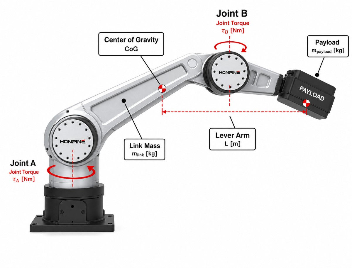
T = m × g × L
where T represents gravitational torque, m represents the downstream mass, g represents gravitational acceleration, and L represents the perpendicular distance between the joint axis and the center of mass.
This equation shows why the required torque cannot be determined from payload alone. The mass of the robot's own links and components can become a significant part of the torque requirement, particularly when the arm operates in extended positions.
A proper joint-sizing process should therefore begin with the mechanical structure rather than the product catalog.
2. Payload Is Only One Part of the Joint Load
When a robotic arm is described as having a certain payload capacity, it is easy to assume that the payload determines the required joint torque.
In reality, the joint is responsible for moving the complete downstream assembly.
Depending on the robot structure, this may include the payload, end-effector, links, bearings, cables, sensors, and other joint modules located farther along the arm.
The further a mass is located from a joint axis, the greater its contribution to gravitational torque.
For example, when a robotic arm extends horizontally, the distance between the joint axis and the downstream center of mass can increase significantly. The same payload that produces a relatively small torque when the arm is folded can create a much larger torque when the arm is fully extended.
This means that joint sizing should consider representative and worst-case robot postures rather than relying on a single nominal position.
The practical question is not simply:
"What is the payload of the robot?"
It is:
"What total downstream mass must this joint move, and where is that mass located under the most demanding operating condition?"
This distinction is fundamental when designing a reliable robotic arm.
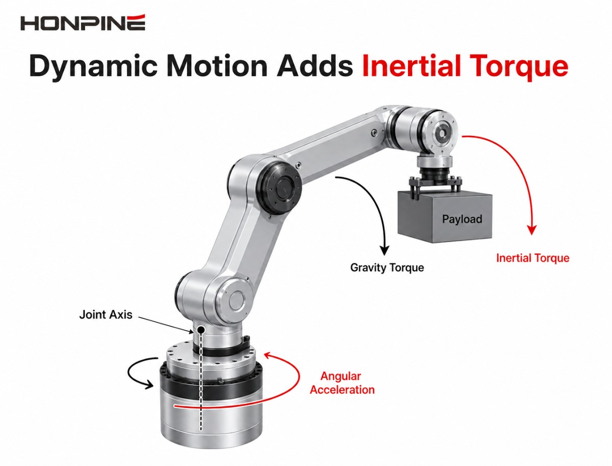
3. Dynamic Motion Adds Inertial Torque
Static torque calculations provide a useful starting point, but they are not sufficient for a robotic arm that needs to accelerate and decelerate quickly.
During dynamic motion, the joint must also generate torque to accelerate the rotational inertia of the downstream structure.
The basic relationship is:
T_inertia = J × α
where J represents the equivalent rotational inertia and α represents angular acceleration.
The total torque requirement can therefore be considered as:
T_required = T_gravity + T_inertia + T_external
The external term may include forces generated by the end-effector, process loads, cable forces, or other application-specific disturbances.
This is particularly important when the robotic arm is designed for high-speed pick-and-place, machine tending, assembly, inspection, or other applications with frequent acceleration and deceleration.
A joint that appears adequate under static conditions may require significantly more torque during dynamic operation.
For this reason, engineers should use the actual motion profile whenever possible. Maximum speed alone does not determine the dynamic torque requirement. Acceleration, deceleration, payload distribution, and the rotational inertia of the moving structure can be equally important.
4. Joint Mass Can Change the Requirements of the Entire Robot
One of the most important considerations in robot joint sizing is the mass of the selected joint itself.
When a joint module is installed in a robotic arm, its weight becomes part of the downstream load of other joints.
This means that selecting a heavier joint can change the torque requirement of the entire mechanical system.
Consider a simple example. If a heavier joint is installed near the end of the robotic arm, its mass contributes to the load that must be accelerated by the joints closer to the robot base. If the additional mass requires a larger upstream joint, the upstream joint itself becomes heavier, which can increase the load again.
This creates a system-level relationship between joint size and robot mass.
The effect becomes even more significant when considering rotational inertia. For a simplified point mass, rotational inertia can be approximated as:
J = m × r²
where m is mass and r is the distance from the rotation axis.
Because distance is squared, a relatively small increase in distal mass can have a disproportionately large effect on the inertia seen by an upstream joint.
This is why choosing a joint with excessive torque capacity can sometimes reduce overall robot performance instead of improving it.
The best joint is generally the one that provides enough performance without adding unnecessary mass.
5. Torque Density Is a Key Parameter for Robotic Arm Design
For robotic arms, maximum torque is important, but it should not be considered in isolation.
Torque density provides another useful way to compare robot joint modules.
In practical terms, torque density describes how much output torque a joint can provide relative to its mass or physical volume.
A joint with high torque density can provide the required output torque while maintaining a compact and lightweight robotic structure.
This is particularly valuable when the joint is installed away from the robot base.
Reducing distal mass can lower the torque and inertia requirements of upstream joints. As a result, the benefit of a lightweight, high-torque-density joint can extend beyond the individual axis where it is installed.
For example, if a compact harmonic joint module can provide the required torque with less mass than a larger alternative, the reduction in distal weight can improve the overall mechanical balance of the robotic arm.
This can contribute to higher acceleration, lower energy consumption, reduced structural loading, and improved dynamic response.
Therefore, when comparing candidate robot joint motors or harmonic robot joint modules, engineers should consider the relationship between output torque, joint mass, physical dimensions, and actual application requirements.
6. Do Not Oversize Every Joint for the Same Reason
Using an oversized joint throughout the robotic arm may appear to simplify engineering because the same product can be used across multiple axes.
However, this approach can introduce unnecessary mass and cost.
A joint that is appropriate for a high-load axis may be excessive for a lower-load axis. Installing that larger joint where it is not required increases the mass of the robot without necessarily improving its useful performance.
The additional mass can also increase the load on the other joints.
For a robotic arm manufacturer, the better objective is to create a standardized joint platform with several suitable size and torque classes.
This allows the same basic mechanical and electrical design philosophy to be maintained while selecting different joint capacities according to the actual requirements of each axis.
Standardization can reduce engineering and production complexity, but standardization does not mean that every axis should use exactly the same joint.
The ideal approach is to minimize the number of joint variants while still maintaining an appropriate torque-to-weight balance.
7. Mechanical Size Must Be Evaluated Together With Torque
A robot joint module must fit inside the robotic arm structure, but a compact external dimension should not be evaluated separately from the required mechanical performance.
The available installation space, mounting interface, joint length, output structure, bearing arrangement, cable routing, and surrounding components all influence the final joint design.
A joint with sufficient torque but excessive axial length may require a major redesign of the arm structure.
Similarly, a compact joint may fit mechanically but lack sufficient continuous torque or thermal capacity for the intended duty cycle.
This is why joint selection should be performed together with the mechanical design.
For each candidate module, engineers should compare the product's torque and speed characteristics with its overall dimensions and mass. The objective is to determine whether the joint can meet the robot's performance requirements within the available mechanical envelope.
For compact robotic arms, this balance between torque, mass, diameter, and installation volume can be more important than any single specification.
8. Continuous Torque and Peak Torque Should Be Evaluated From the Motion Profile
The torque requirement of a robotic arm is not constant during operation.
Different robot postures and motion phases can produce significantly different loads.
During acceleration, the required torque can increase because the joint must overcome rotational inertia. During a sustained static posture, gravitational torque may become the dominant factor. During rapid deceleration, the system may experience another high-torque condition.
For this reason, engineers should distinguish between continuous and peak operating requirements.
A joint may have enough peak torque for a short acceleration event but still be unsuitable for continuous operation if its thermal capacity is insufficient.
Conversely, selecting a very large joint simply to increase peak torque capacity may introduce unnecessary mass.
The correct approach is to compare the joint's continuous and peak capabilities against the actual robot motion profile.
For applications involving repetitive cycles, the duty cycle should also be considered because the average thermal load can be very different from the instantaneous peak load.
9. Joint Selection Should Be Verified Through the Complete Robot Model
Initial torque calculations are only the beginning.
Once candidate joint modules have been selected, their actual mass and dimensions should be incorporated into the robotic arm model.
This is important because the selected joint becomes part of the mechanical system.
For example, if the initial calculation assumes a 1 kg joint but the selected product weighs 1.8 kg, the downstream mass calculation should be updated. The additional mass can change the required torque of upstream joints.
The same principle applies to the center of gravity and rotational inertia.
A practical engineering workflow is therefore iterative. The designer first estimates the required torque, selects a suitable joint, updates the robot model with the actual joint mass and dimensions, recalculates the system requirements, and then confirms whether the selected modules remain appropriate.
This approach is more reliable than selecting all joints once and assuming the original calculations remain valid.
10. A Practical Example: Sizing a 6-Axis Robotic Arm
Consider a 6-axis robotic arm with approximately 2 kg payload and a reach of around 500 mm.
These two numbers alone are not sufficient to determine the correct joint modules. The link masses, joint masses, end-effector weight, payload center of gravity, acceleration, speed, and robot posture must also be considered.
The design process can begin by creating a simplified mechanical model of the arm.
For each joint, calculate the total downstream mass and its center of gravity. Then determine the gravitational torque under the most demanding representative postures.
Next, calculate the inertial torque based on the required angular acceleration.
The resulting torque requirement can then be compared with candidate joint modules while considering their mass, diameter, length, speed, stiffness, and thermal characteristics.
After selecting preliminary modules, add their actual masses to the robot model and repeat the calculation.
This iterative process may reveal that an apparently attractive high-torque joint is unnecessarily heavy, or that a smaller joint with higher torque density provides a better overall solution.
The final selection should therefore be based on the complete robotic arm rather than on isolated product specifications.
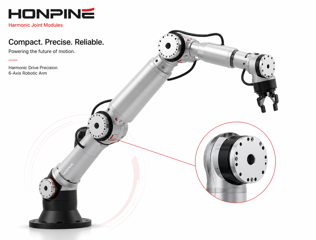
11. How Harmonic Joint Modules Support Compact Robotic Arms
Harmonic transmission is widely used in robotic motion systems because it can provide high reduction ratios, compact dimensions, high torque density, and low backlash.
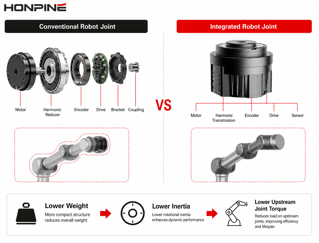
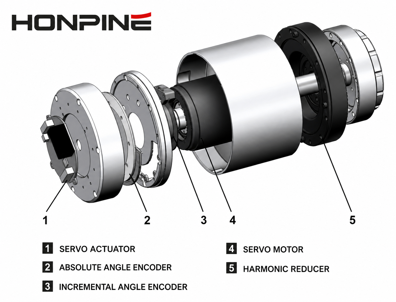
When integrated into a robot joint module, the harmonic transmission can be combined with a motor, encoder, and other functions required by the robot architecture.
The value of this integration is particularly apparent when the robot has limited installation space.
A compact harmonic joint actuator can reduce the number of separate components that need to be packaged into the robot structure and can simplify mechanical integration.
However, the appropriate harmonic joint should still be selected according to the actual requirements of the robot.
Reduction ratio, output torque, speed, joint mass, dimensions, stiffness, thermal performance, encoder configuration, and control interface should all be considered within the system design.
The purpose of an integrated joint is not simply to combine multiple components into one housing. It is to provide a practical motion unit that can be incorporated into the mechanical and control architecture of the robotic arm.
12. Electrical and Control Integration Should Be Considered During Mechanical Design
Although this article focuses on mechanical sizing, electrical integration should not be postponed until after the mechanical design is complete.
The selected robot joint module needs to work with the robot's power supply, controller, communication architecture, and feedback system.
For an integrated joint, engineers should confirm the required supply voltage, current capability, communication interface, encoder configuration, driver architecture, and available feedback data.
This information can affect the overall robot architecture, particularly when multiple joint modules operate from a common DC power system.
The physical routing of power and communication cables should also be considered during the mechanical design. A joint that provides a suitable internal cable path can simplify the packaging of the complete robotic arm.
The key principle is to evaluate mechanical and electrical integration together rather than treating the joint as an isolated motor component.
13. A System-Level Approach to Robot Joint Sizing
A reliable robot joint sizing process can be summarized through several connected engineering stages.
The first stage is to define the robot geometry and operating conditions. This includes link dimensions, mass distribution, payload, end-effector, speed, acceleration, and working cycle.
The second stage is to calculate the static and dynamic torque requirements of each axis.
The third stage is to compare candidate joint modules according to torque, speed, mass, dimensions, stiffness, and thermal capability.
The fourth stage is to incorporate the selected joint masses into the complete mechanical model and recalculate the upstream requirements.
The fifth stage is to verify the final configuration under the robot's actual operating conditions, including representative postures, acceleration, continuous operation, and thermal load.
This process prevents a common design mistake in which each joint is selected independently without considering its effect on the complete robotic arm.
14. How HONPINE Approaches Robot Joint Module Selection
HONPINE provides harmonic reducers, harmonic joint motors, harmonic rotary actuators, planetary reducers, and integrated motion solutions for robotic and industrial automation applications.
For robotic arm projects, joint selection can be evaluated according to the actual requirements of the mechanical system rather than simply matching a payload number to a motor torque rating.
The key parameters include payload, arm reach, link mass, joint speed, acceleration, duty cycle, installation dimensions, required torque, power supply, and control architecture.
These parameters can be used to evaluate the appropriate combination of motor, harmonic transmission, encoder, drive architecture, and mechanical interface.
For custom robotic applications, the joint selection process can begin with the robot's mechanical model and load requirements. Candidate joint modules can then be evaluated according to their torque capacity, mass, dimensions, speed, and integration requirements.
This approach allows the joint architecture to be optimized together with the robotic arm instead of treating the joint as an independent component.
15. Robot Joint Module Sizing Checklist
Before finalizing a robot joint module, engineers should verify the complete relationship between the joint and the robotic arm.
The downstream mass should be calculated for each axis, including the payload, end-effector, links, cables, sensors, and other components that the joint needs to move. The center of gravity should be considered under representative and worst-case robot postures.
Static gravitational torque and dynamic inertial torque should be calculated separately. The required continuous torque and peak torque should then be compared with the actual operating cycle.
The mass of the selected joint should be incorporated into the complete robot model because it can change the torque and inertia requirements of upstream joints.
Engineers should also compare torque density, joint dimensions, speed, stiffness, thermal capability, mechanical interface, cable routing, power supply, and control compatibility.
The final objective is to select a joint that satisfies the robot's performance requirements without adding unnecessary mass or mechanical complexity.
Conclusion
Sizing a robot joint module for a robotic arm is a system-level engineering problem.
Payload is only one part of the calculation. The joint must also move the downstream links, end-effector, cables, sensors, and other components. During dynamic operation, rotational inertia and acceleration create additional torque requirements. At the same time, the mass of the selected joint can affect the load and inertia experienced by other joints.
This is why simply choosing the highest-torque joint is rarely the best design strategy.
A more effective approach is to calculate the load of each axis, evaluate gravitational and inertial torque, consider the mass and torque density of candidate joint modules, and then verify the complete robotic arm with the selected components included in the mechanical model.
For compact and precision robotic arms, a properly sized harmonic robot joint module can provide a useful combination of compact packaging, high torque density, high reduction ratio, and precise rotary motion.
The goal is not to make every joint as powerful as possible.
The goal is to create a balanced joint architecture in which each module provides the required performance while keeping the complete robotic arm lightweight, responsive, and mechanically efficient.
HONPINE provides harmonic transmission and integrated motion solutions for robotic and automation applications. For a specific robotic arm project, providing the payload, reach, link mass, joint speed, acceleration, duty cycle, and installation requirements can provide a solid basis for evaluating the appropriate robot joint module.
Read More
Learn more about the story of HONPINE and industry trends related to precision transmission.
 What is robot joint actuator?How to Choose the Best Robot Rotary Joint Actuator?In core robot joint transmission solutions, planetary and harmonic rotary actuators each have their own strengths. Choosing the right type based on application requirements is essential to achieve the optimal balance between performance and cost.
 DD Motors VS Harmonic Rotary ActuatorsThis article provides an in-depth comparison between Direct Drive (DD) motors and harmonic rotary actuators, covering their transmission principles, advantages and disadvantages, and typical application fields.
 OMG Ultra Compact Harmonic Drive Joint Module with Built-in Torque SensorHONPINE TCHL series harmonic drive joint module is a game-changing product that achieves disruptive improvements in multiple aspects such as lightweight design, integration level, and connection convenience. This article will analyze its revolutionary enhancements with you.
 The Role of Harmonic Drive Gears in Achieving 5–10 μm Accuracy in Dental Milling MachinesA dental milling machine is a CNC machining system used to directly process digital dental models into restorations such as crowns, bridges, veneers, inlays, and implant abutments. Dental milling machines require far higher operational accuracy and motion stability than ordinary equipment. This article explains how harmonic drive gear help dental milling machines achieve stable, continuous, and controllable operation.
 Why Are Harmonic Rotary Actuators Perfect for Medical Equipment?Harmonic rotary actuators (typically integrated systems consisting of a harmonic drive reducer, frameless torque motor, encoder, and optional brake) are regarded as key components in medical equipment. The core reason is that they simultaneously meet the most stringent medical requirements for precision, compact size, safety, and controllability. The following explanation is structured from three perspectives: technical characteristics, application scenarios, and medical value.
 High-Precision RV Reducers Perfectly Matched for Walking RobotsThe walking axis of a robot is a core component for power transmission and support. RV reducers provide extremely high rigidity, precision, and torque while maintaining a compact size and exceptional reliability, making them an ideal match for the demanding requirements of walking robot joints in terms of load capacity, impact resistance, and precision.
 How to Choose a Robot Joint Motor for Better End-Effector Performance?
Choosing a robot joint motor is not only about selecting the highest torque or the smallest joint. The performance of a robotic arm is ultimately determined by what happens at the end-effector. Tool mass, payload, center of gravity, rotational inertia, motion speed, acceleration, and settling performance can all influence the requirements of each robot joint. Depending on the application, a harmonic joint motor or planetary joint motor may provide a different balance between torque, speed, compactness, and system dynamics. This article explains how to select a robot joint motor by starting with end-effector requirements and evaluating the complete robotic arm as a motion system. How to Size Robot Joint Modules for a Robotic Arm? A Practical Engineering Guide?Choosing a suitable robot joint module is one of the most important decisions when designing a robotic arm. The right selection is not determined by payload or rated torque alone. Link mass, center of gravity, rotational inertia, acceleration, joint weight, torque density, installation space, and operating cycle can all affect the final joint requirements. An oversized joint may increase the robot's mass and inertia, while an undersized joint can limit motion performance and reliability. This guide explains a practical engineering approach to selecting a robot joint module, helping robotic arm designers evaluate torque, weight, dimensions, dynamic performance, and system integration before finalizing their joint architecture.
 Ultra-Thin Direct Drive Rotary Actuator for High-Precision Automation and InspectionDiscover how an ultra-thin direct drive rotary actuator and direct drive rotary motor improve positioning accuracy, smooth motion, and compact machine integration for semiconductor inspection, AOI systems, optical alignment, chip sorting, photovoltaic wafer inspection, and precision automation equipment.
 Robot Joint Motor with Dual Encoders: How to Reduce Harmonic Reducer Backlash and Improve Position AccuracyA high-performance robot joint motor is more than a motor combined with a harmonic reducer. Actual robot joint position accuracy depends on the complete motion chain, including transmission characteristics, mechanical stiffness, encoder feedback, load variation, and control performance. Although a harmonic reducer can achieve extremely low backlash, low backlash does not automatically guarantee perfect output accuracy. A dual encoder robot joint motor adds direct output-side feedback to motor-side position measurement, allowing the control system to better understand actual joint movement and reduce the effects of transmission error and load-dependent deformation. This article explains how dual encoders can improve robot joint position accuracy in high-precision and high-dynamic applications.
 Why Humanoid Robot Joint Actuators Are Becoming Critical as More Industries Enter Humanoid Robotics?Humanoid robotics is no longer driven only by traditional robot manufacturers. Automotive companies, AI companies, logistics providers, consumer electronics manufacturers, and advanced technology enterprises are increasingly entering the humanoid robot market. However, artificial intelligence can only create real value when digital intelligence can be converted into reliable physical movement. This makes the humanoid robot joint actuator a critical interface between AI, motion control, and the physical robot body. This article explores why harmonic drive actuators, high torque density, low backlash, integrated feedback, and scalable joint architectures are becoming increasingly important as humanoid robotics moves from prototype development toward large-scale commercialization.
 Rotary Joints for Robots: Which Joint Architecture Fits Your Robot Design?Modern rotary joints for robots are no longer simply mechanical connections between two robot links. A robot joint must increasingly combine torque generation, motion transmission, position feedback, communication, sensing, braking, and control integration within a compact and reliable structure. As humanoid robots, collaborative robots, industrial robotic arms, medical robots, and specialized robotic systems continue to evolve, selecting the right robot joint module and joint architecture has become a system-level engineering decision. This article explores how integrated harmonic joint modules and planetary joint modules provide different solutions and how robot manufacturers can choose the right architecture for each robot axis.

Double Click
We provide harmonic drive reducer,planetary reducer,robot joint motor,robot rotary actuators,RV gear reducer,robot end effector,dexterous robot hand
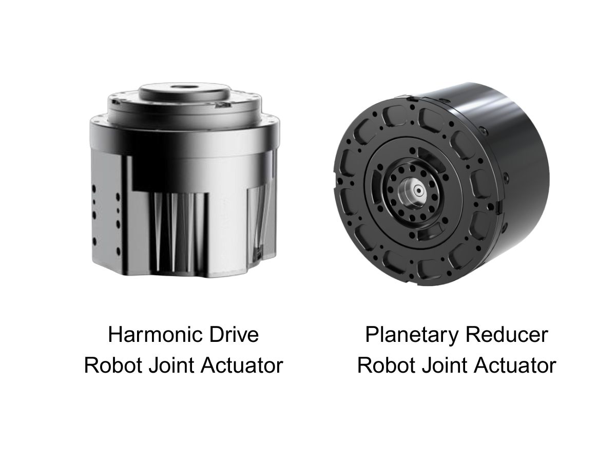
 What is robot joint actuator?How to Choose the Best Robot Rotary Joint Actuator?In core robot joint transmission solutions, planetary and harmonic rotary actuators each have their own strengths. Choosing the right type based on application requirements is essential to achieve the optimal balance between performance and cost.
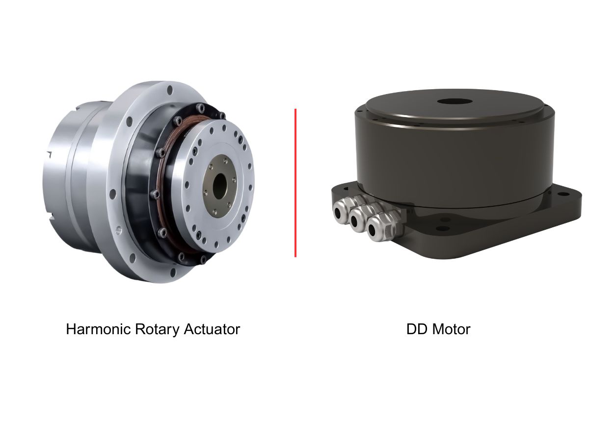
 DD Motors VS Harmonic Rotary ActuatorsThis article provides an in-depth comparison between Direct Drive (DD) motors and harmonic rotary actuators, covering their transmission principles, advantages and disadvantages, and typical application fields.
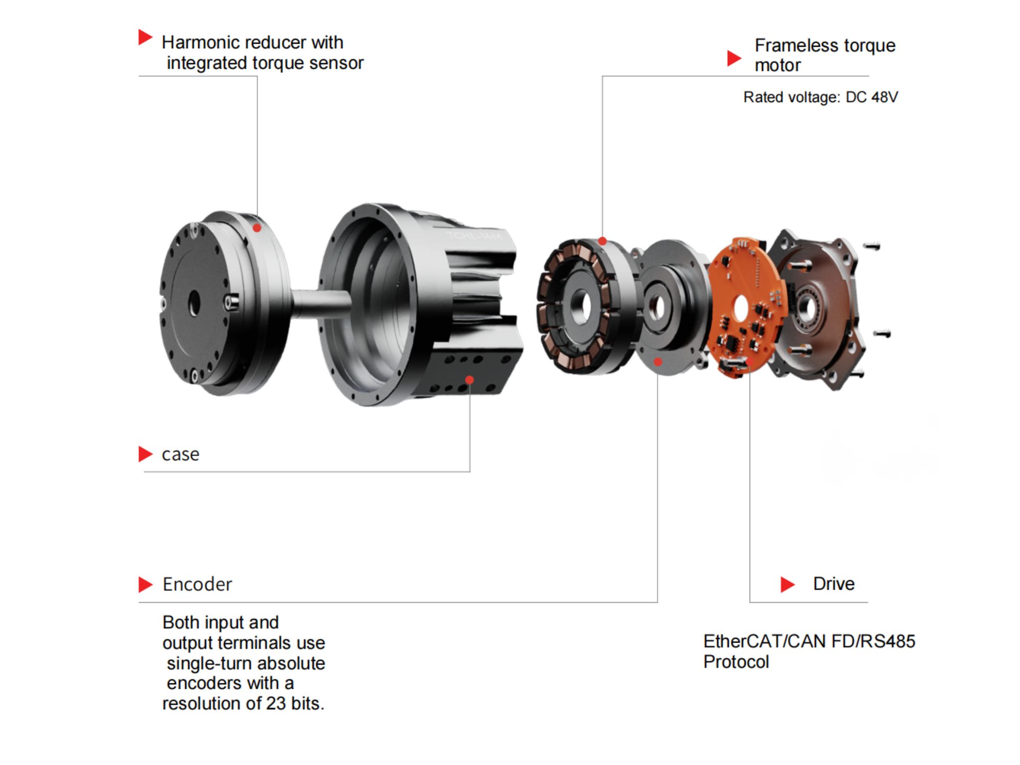
 OMG Ultra Compact Harmonic Drive Joint Module with Built-in Torque SensorHONPINE TCHL series harmonic drive joint module is a game-changing product that achieves disruptive improvements in multiple aspects such as lightweight design, integration level, and connection convenience. This article will analyze its revolutionary enhancements with you.
 How to Choose a Robot Joint Motor for Better End-Effector Performance?
Choosing a robot joint motor is not only about selecting the highest torque or the smallest joint. The performance of a robotic arm is ultimately determined by what happens at the end-effector. Tool mass, payload, center of gravity, rotational inertia, motion speed, acceleration, and settling performance can all influence the requirements of each robot joint. Depending on the application, a harmonic joint motor or planetary joint motor may provide a different balance between torque, speed, compactness, and system dynamics. This article explains how to select a robot joint motor by starting with end-effector requirements and evaluating the complete robotic arm as a motion system. How to Size Robot Joint Modules for a Robotic Arm? A Practical Engineering Guide?Choosing a suitable robot joint module is one of the most important decisions when designing a robotic arm. The right selection is not determined by payload or rated torque alone. Link mass, center of gravity, rotational inertia, acceleration, joint weight, torque density, installation space, and operating cycle can all affect the final joint requirements. An oversized joint may increase the robot's mass and inertia, while an undersized joint can limit motion performance and reliability. This guide explains a practical engineering approach to selecting a robot joint module, helping robotic arm designers evaluate torque, weight, dimensions, dynamic performance, and system integration before finalizing their joint architecture.
 Ultra-Thin Direct Drive Rotary Actuator for High-Precision Automation and InspectionDiscover how an ultra-thin direct drive rotary actuator and direct drive rotary motor improve positioning accuracy, smooth motion, and compact machine integration for semiconductor inspection, AOI systems, optical alignment, chip sorting, photovoltaic wafer inspection, and precision automation equipment.
 Robot Joint Motor with Dual Encoders: How to Reduce Harmonic Reducer Backlash and Improve Position AccuracyA high-performance robot joint motor is more than a motor combined with a harmonic reducer. Actual robot joint position accuracy depends on the complete motion chain, including transmission characteristics, mechanical stiffness, encoder feedback, load variation, and control performance. Although a harmonic reducer can achieve extremely low backlash, low backlash does not automatically guarantee perfect output accuracy. A dual encoder robot joint motor adds direct output-side feedback to motor-side position measurement, allowing the control system to better understand actual joint movement and reduce the effects of transmission error and load-dependent deformation. This article explains how dual encoders can improve robot joint position accuracy in high-precision and high-dynamic applications.
 Why Humanoid Robot Joint Actuators Are Becoming Critical as More Industries Enter Humanoid Robotics?Humanoid robotics is no longer driven only by traditional robot manufacturers. Automotive companies, AI companies, logistics providers, consumer electronics manufacturers, and advanced technology enterprises are increasingly entering the humanoid robot market. However, artificial intelligence can only create real value when digital intelligence can be converted into reliable physical movement. This makes the humanoid robot joint actuator a critical interface between AI, motion control, and the physical robot body. This article explores why harmonic drive actuators, high torque density, low backlash, integrated feedback, and scalable joint architectures are becoming increasingly important as humanoid robotics moves from prototype development toward large-scale commercialization.
 Rotary Joints for Robots: Which Joint Architecture Fits Your Robot Design?Modern rotary joints for robots are no longer simply mechanical connections between two robot links. A robot joint must increasingly combine torque generation, motion transmission, position feedback, communication, sensing, braking, and control integration within a compact and reliable structure. As humanoid robots, collaborative robots, industrial robotic arms, medical robots, and specialized robotic systems continue to evolve, selecting the right robot joint module and joint architecture has become a system-level engineering decision. This article explores how integrated harmonic joint modules and planetary joint modules provide different solutions and how robot manufacturers can choose the right architecture for each robot axis.
 Harmonic Rotary Actuator for High Precision Positioning: What Really Determines Positioning Accuracy?When engineers search for a Harmonic Rotary Actuator for High Precision Positioning, the first question is often how accurate the actuator itself can be. In practice, however, positioning accuracy is determined by much more than the reducer or actuator specification. Harmonic transmission accuracy, backlash characteristics, torsional stiffness, encoder feedback, bearing support, load inertia, servo tuning, installation quality, and external disturbances can all influence the final position of the load.
 10 Robot Joint Module Challenges and Solutions for Lightweight and Special-Purpose RobotsThe development of humanoid robots, collaborative robots, lightweight robotic arms, medical robots, mobile manipulators, and special-purpose robotic systems is creating new challenges for robot joint design. Engineers must balance torque, weight, stiffness, precision, sensing, cable routing, control, safety, and limited installation space within the same joint. A conventional motor-and-reducer combination may meet individual specifications but still become difficult to integrate into the complete robot. This article examines 10 common Robot Joint Module challenges and the engineering solutions that can help developers create lighter, more compact, precise, and application-specific robotic systems. From torque density and integrated sensing to hollow-shaft cable routing, flexible mounting, and control integration, the focus is on how the joint architecture can better match the actual requirements of the robot.
 RV Gearbox for Industrial Robots: How to Match Load, Precision, and Service Life for Different ApplicationsAn RV Gearbox plays an important role in determining the load capacity, positioning performance, structural rigidity, and service life of an industrial robot. However, selecting the right RV Gearbox cannot be reduced to comparing rated torque or reduction ratios. Different applications such as palletizing, welding, machining, casting, and precision assembly expose robot joints to very different load spectra, motion profiles, external forces, and duty cycles. A gearbox that performs well in one robot axis may not be suitable for another. This article examines how engineers can match an RV Gearbox to real operating conditions, including load spectrum, inertia, rigidity, precision, and expected service life, while also considering when harmonic reducers or integrated robot joint motors may provide a better solution.